Method for producing dihydroxy compounds

A technology of dihydroxy compounds and uses, which is applied in the field of manufacturing polycarbonate and producing phenol A, can solve the problem of uneven flow distribution in the reactor, etc., and achieve the effect of reducing dead space and good flow distribution

Pending Publication Date: 2019-04-02
SABIC GLOBAL TECH BV
View PDF9 Cites 1 Cited by
  • Summary
  • Abstract
  • Description
  • Claims
  • Application Information

AI Technical Summary

Problems solved by technology

[0010] The inventors have found that existing reactors for the production of dihydroxy compounds suffer from limited throughput, etc. due to pressure drop limitations
Furthermore, the inventors found that the flow distribution throughout the existing reactor was not uniform enough

Method used


Image

  • Method for producing dihydroxy compounds
  • Method for producing dihydroxy compounds
  • Method for producing dihydroxy compounds

Examples


Embodiment 1

[0082] Example 1: Basic shell reactor with two distributors (comparative)

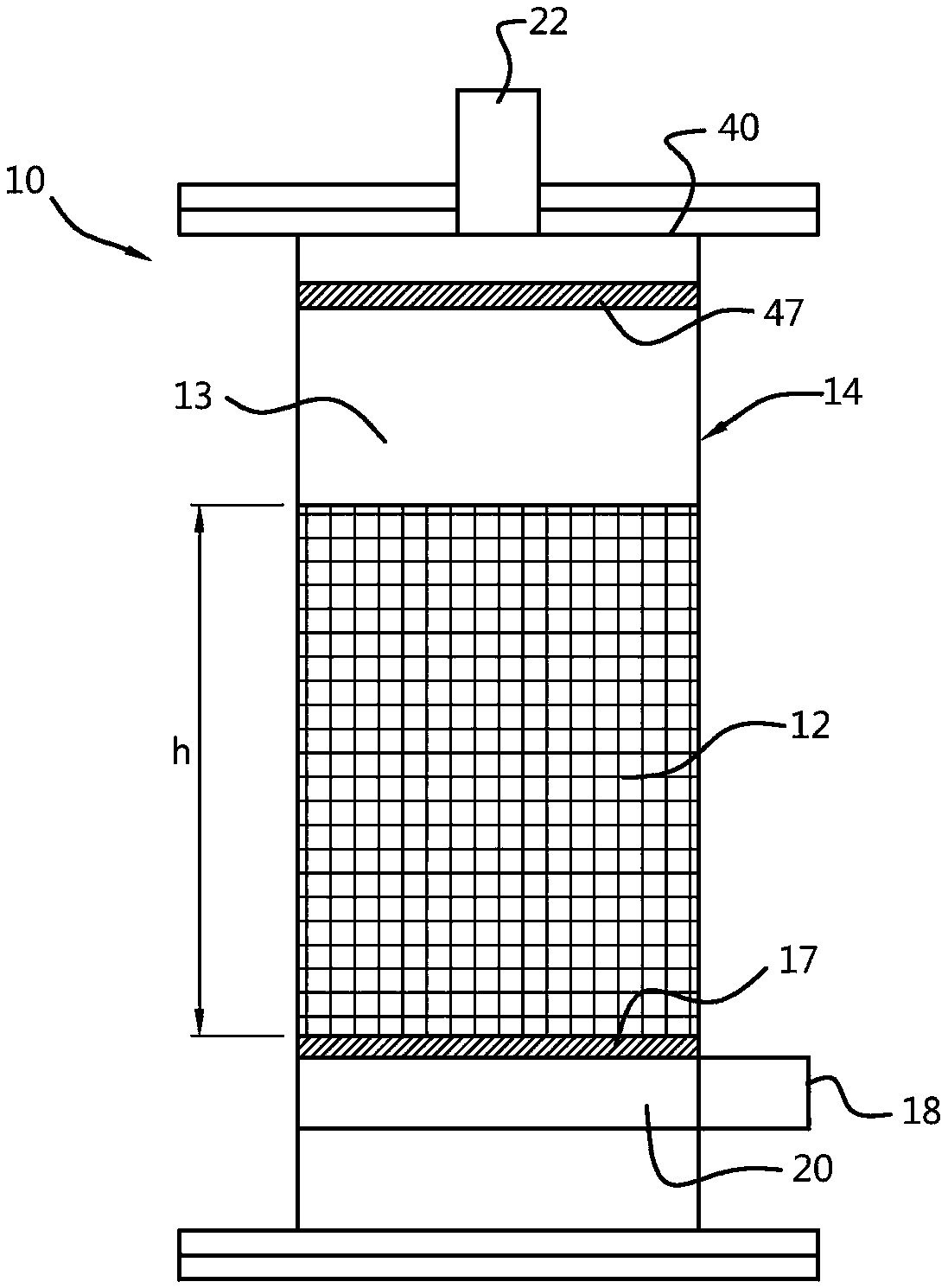
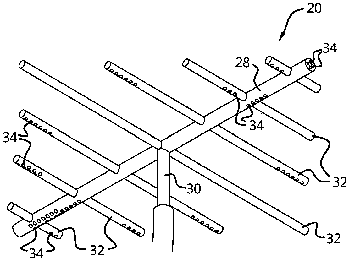
[0083] The basic shell design consists of four side feed tubes and two distributors. The four feed tubes were modeled with 46 perforations with a diameter of 10mm. The longer tube was modeled with 13 perforations spaced at 5 cm intervals and the shorter tube was modeled with 10 perforations at the same spacing. Initially, the perforations are made on the upper side (upwards) of the tube. The distributor plate was modeled with 3825 smaller perforations with a diameter of 5 mm. The thickness of the distributor screen is 7 mm.

[0084] Cold flow simulations were performed on the geometry with the design as explained in the previous paragraph and the results are shown in Figure 8 and 9 middle. Figure 8 Velocity profiles of the base shell design on the mid-axis section (left) and at the mid-section (right) are shown. The velocity profile at the shaft section shows developing flow, and the velocity ...

Embodiment 2

[0085] Example 2: Changing the direction of the piercing to dissipate momentum

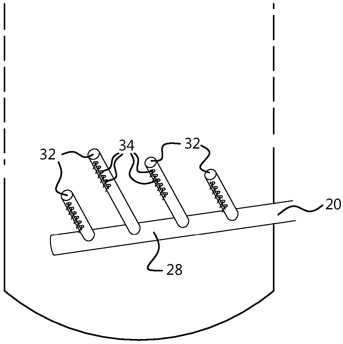
[0086] Based on the simulation results discussed in Example 1, it was concluded that the high velocity plaque was due to the fact that more fluid was trying to pass through the first perforation since it was the lower resistance path. This results in high local velocities at the first hole. By dissipating momentum with impingement plates, the effect of high velocity plaque on the catalyst bed can be minimized. It was decided to use the bottom wall of the section as an impact plate to dissipate this momentum. This requires placing perforations in the bottom face of the side pipes so that fluid travels down from these pipes and hits the bottom wall and dissipates momentum. Modifications were made to the geometry model to achieve this and advance computational fluid dynamics (CFD) simulations. A snapshot of the improved geometry with a perforation on the underside of the feed tube is shown in Fi...

Embodiment 3

[0088] Example 3: Effect of the number of distributor screens

[0089] Geometry models were developed using one and two distributor screens and CFD simulations were performed to understand the effect of additional distributor screens. Figure 13 Simulation results are shown. It is evident that the distributor screen at the bottom is mainly used to support the catalyst bed and also to help redistribute the fluid. However, without the support of CFD modeling, the role / need for the top sparger screen is called into question. Based on the simulation results, it was found that the top sparger screen acts to maintain a uniform flow even after the reaction section. Consequently, the dead space in the reactor is significantly reduced. This is critical for a good residence time distribution. exist Figure 13 In , the simulation results for a single sparger screen are compared to those for two sparger screens, and it is evident that the dead space is smaller when the top sparger sc...


PUM

PropertyMeasurementUnit
diameteraaaaaaaaaa
particle diameteraaaaaaaaaa
diameteraaaaaaaaaa

Abstract

The invention is directed to the use of an upflow reactor for producing a dihydroxy compound, to a method for producing a dihydroxy compound, and to a method for manufacturing polycarbonate. The upflow reactor for producing a dihydroxy compound of the invention comprises: a vessel; a catalyst bed disposed in said vessel; a distributor in fluid communication with an inlet through which reactants are introduced to said distributor, said distributor being disposed at a lower end of said vessel and comprising distributor perforation(s) disposed in said distributor, at least part of which distributor perforations are in a direction facing away from said catalyst bed; and a collector through which said product dihydroxy compound is removed, said collector being disposed at an upper end of said vessel.

Description

technical field [0001] The present invention relates to the use of an upflow reactor (upflow reactor) for the production of dihydroxy compounds, to a method for the production of dihydroxy compounds and to a process for the manufacture of polycarbonate method. More specifically, the present invention relates to the production of phenol A by introducing a ketone and a phenolic compound in an upflow reactor. Background technique [0002] Dihydroxy compounds, especially bisphenols, are used as raw materials for the manufacture of chemical products such as epoxy resins and polycarbonates. They are usually prepared by condensation of ketones and phenols. Typical bisphenols include 2,2-bis(4-hydroxyphenyl)propane (also known as bisphenol A), which can be produced by reacting acetone (also known as dimethyl ketone) and phenol in the presence of an acid preparation. [0003] Packed bed reactor systems for the production of bisphenols generally include a bed of packing material (...

Claims


Application Information

Patent Timeline
Patent Type & Authority Applications(China)
IPC IPC(8): B01J8/20B01J4/00B01J8/02
CPCB01J4/004B01J8/025B01J8/0278B01J2208/00911B01J8/0025B01J8/0292B01J2208/06C07C37/60C07C39/16
Inventor 苏里亚·普拉卡萨·拉奥·达利帕尔蒂保卢斯·约翰内斯·马里亚·埃斯鲍茨
Owner SABIC GLOBAL TECH BV
Why Eureka
Try Eureka