Dual-light-source high-precision anti-interference large-working-distance self-collimating device and method
A high-precision, dual-light source technology, applied in the direction of optical devices, measuring devices, optics, etc., can solve the problems of unstable beam transmission, measuring distance not too far, wave front distortion, etc., to increase anti-interference ability and improve anti-interference ability Effect of interference ability and improvement of measurement accuracy
- Summary
- Abstract
- Description
- Claims
- Application Information
AI Technical Summary
Problems solved by technology
Method used
Image

Examples
specific Embodiment 1
[0042] This embodiment is the first specific embodiment of a dual-light source high-precision anti-interference and large working distance self-collimation device.
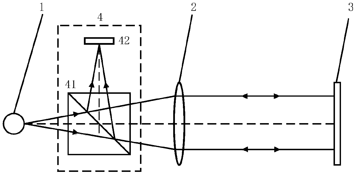
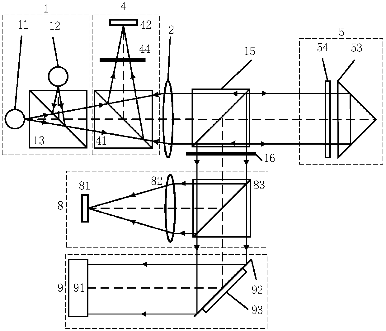
[0043] The dual-light source high-precision anti-interference and large working distance self-collimation device in this embodiment has a schematic structural diagram as shown in figure 2 shown. The self-collimation device includes a light source unit 1, a feedback imaging unit 4, a first transmissive collimator mirror 2, a combined mirror 5, a sixth beam splitter 15, a second optical filter 16, and an angular drift feedback measurement unit 8 , and a wavefront distortion feedback measurement unit 9 .
[0044] The device includes a first light source 11 , a second light source 12 , a first dichroic mirror 54 , a first filter 44 , and a second filter 16 . The first light source 11 and the second light source 12 can emit light beams of two different wavelengths. The first dichroic mirror 54 presents high reflect...
specific Embodiment 2
[0067] This embodiment is the second specific embodiment of a portable dual-light source high-precision high-frequency response anti-interference large working distance self-collimation device.
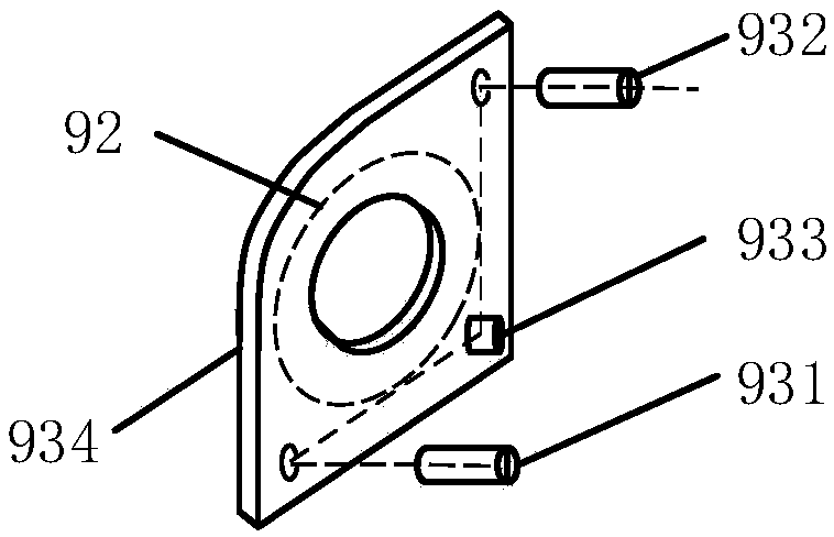
[0068] The portable dual-light source high-precision, high-frequency response, anti-interference, and large working distance self-collimation device in this embodiment, the structural diagram is as follows Figure 4 shown. On the basis of the specific embodiment 1, the first optical filter 44, the sixth beam splitter 15, the second optical filter 16, the second transmissive collimator 82, the fourth feedback beam splitter 92, and the angle adjustment unit 93 are removed , adding the second dichroic mirror 14 and the third transmissive collimator mirror 94. The optical path structure of the disturbance feedback measurement unit is adjusted, the volume of the optical path and optical components is reduced, the overall structure is compact and stable, and it has more advantages of porta...
PUM
 Abstract
Description
Claims
Application Information
 - Generate Ideas
- Intellectual Property
- Life Sciences
- Materials
- Tech Scout
- Unparalleled Data Quality
- Higher Quality Content
- 60% Fewer Hallucinations
Browse by: Latest US Patents, China's latest patents, Technical Efficacy Thesaurus, Application Domain, Technology Topic, Popular Technical Reports.
© 2025 PatSnap. All rights reserved.Legal|Privacy policy|Modern Slavery Act Transparency Statement|Sitemap|About US| Contact US: help@patsnap.com