Photoelectric composite cable for intelligent engineering device

A photoelectric composite cable and engineering equipment technology, applied in the direction of communication cables, insulated cables, power cables, etc., can solve problems such as potential safety hazards, bending and dragging, and short circuits, so as to improve the overall electrical performance, reduce mutual friction, and extend The effect of service life

Inactive Publication Date: 2019-04-09
ANHUI LINGYU CABLE TECH
View PDF14 Cites 8 Cited by
  • Summary
  • Abstract
  • Description
  • Claims
  • Application Information

AI Technical Summary

Problems solved by technology

[0003] However, due to the relatively harsh working environment of coal mining projects, frequent start and stop, multi-stage speed change, and high failure rate during use, especially during night operations, the photoelectric composite cable is easily crushed by the carrying equipment, and it will be frequently damaged during the moving process. Severe bending and dragging of "8" or "S" shape occurs, and the photoelectric composite cable is also impacted by falling coals and stones. Therefore, the sheath and insulation layer of the cable are easily damaged and cracked, and the conductor And the optical fiber is also very easy to break, resulting in the interruption of the signal of the control equipment, short circuit, insulation breakdown or leakage of the line, which eventually...

Method used


Image

  • Photoelectric composite cable for intelligent engineering device
  • Photoelectric composite cable for intelligent engineering device
  • Photoelectric composite cable for intelligent engineering device

Examples


Embodiment Construction

[0027] The following will clearly and completely describe the technical solutions in the embodiments of the present invention with reference to the accompanying drawings in the embodiments of the present invention. Obviously, the described embodiments are only some, not all, embodiments of the present invention. Based on the embodiments of the present invention, all other embodiments obtained by persons of ordinary skill in the art without making creative efforts belong to the protection scope of the present invention.

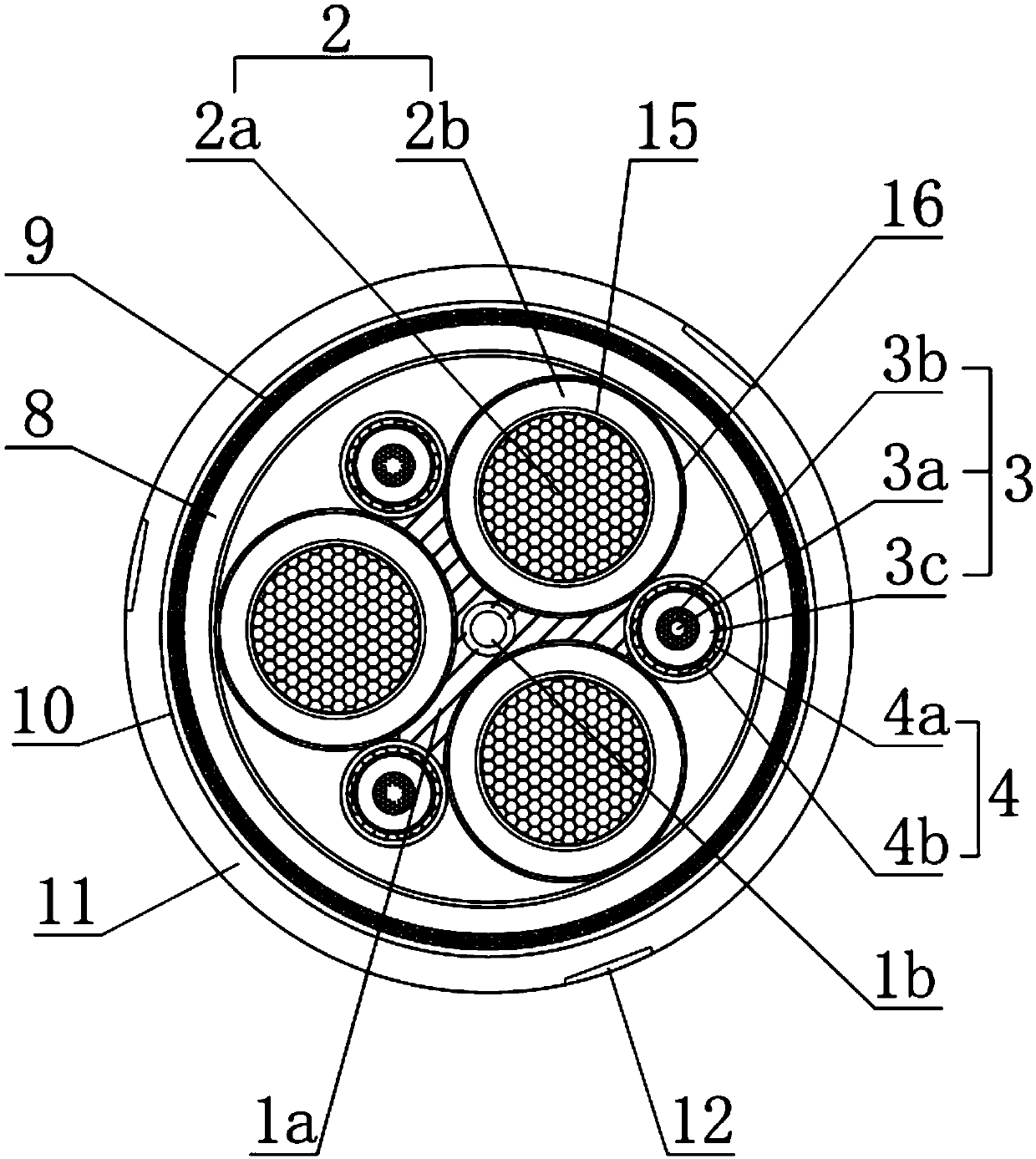
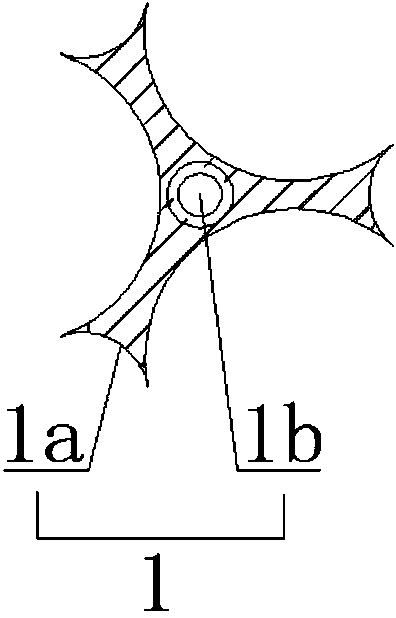
[0028] see Figure 1-3, an embodiment provided by the present invention: a photoelectric composite cable for intelligent engineering equipment, including a special-shaped vulcanized semi-conductive rubber core 1, a power core 2, a control core 3, a monitoring core 4 and a core for wrapping The protective layer, the special-shaped vulcanized semi-conductive rubber cushion core 1 is composed of a "herringbone"-shaped semi-conductive special-shaped support 1a and...


PUM


Abstract

The invention discloses a photoelectric composite cable for an intelligent engineering device. The photoelectric composite cable comprises an irregularly-shaped vulcanized semi-conductive rubber cushion core, a power wire core, a control wire core, a monitoring wire core and a protective layer used for wrapping the wire cores, the irregularly-shaped vulcanized semi-conducive rubber cushion core isformed by an inverted-Y-shaped semi-conductive irregular support and an optical cable unit, the optical cable unit is formed by a tensile element, optical fibers surrounding at the outside of the tensile element, and a stainless steel spiral hose used for wrapping the optical fibers, the power wire core is formed by a power wire core conductor and a power wire core insulating layer used for wrapping the power wire core conductor, and the surface of the control wire core is sleeved by the monitoring wire core. According to the photoelectric composite cable, functions of electric energy transmission, signal control and transmission video communication etc. are provided, special performances including excellent extrusion resistance, impact resistance, bending resistance and direct dragging are also achieved, a night light-reflection function is also provided, the generation of toxic and harmful gas is avoided during combustion of the cable, and the photoelectric composite cable is in accordance with the development concept of green environmental protection.

Description

technical field [0001] The invention relates to the technical field of wire and cable manufacturing, in particular to a photoelectric composite cable for intelligent engineering equipment. Background technique [0002] The photoelectric composite cable is a composite optical fiber unit, which realizes the function of power supply or lightning protection and performs optical fiber communication at the same time. The existing photoelectric composite cable has an optical cable core between the power transmission cores, which can transmit light and electrical signals at the same time. In addition, the existing photoelectric composite cable has the advantages of light weight, convenient construction, and low cost. It is worth noting that Distributed optical fibers are highly sensitive to ambient temperature. Therefore, in high-voltage and ultra-high-voltage cross-linked cables, temperature-sensitive optical fibers are implanted to prepare photoelectric composite cables, and they ...

Claims


Application Information

Patent Timeline
IPC IPC(8): H01B7/00H01B7/02H01B7/18H01B7/22H01B7/29H01B7/295H01B7/36H01B9/02H01B11/00
CPCH01B7/00H01B7/0045H01B7/0225H01B7/1805H01B7/1825H01B7/1875H01B7/22H01B7/292H01B7/295H01B7/36H01B9/021H01B11/00
Inventor 朱峰林闵泽宇
Owner ANHUI LINGYU CABLE TECH
Why Eureka
Try Eureka