Organic liquid flow battery system for aqueous system based on salt cavern

A liquid flow battery and system technology, applied in the direction of fuel cells, aqueous electrolytes, fuel cell additives, etc., can solve problems such as hidden dangers, low Coulombic efficiency, and limited solubility of active materials, and achieve stable charge and discharge performance, high safety performance, The effect of high solubility

Active Publication Date: 2019-04-09
CHINASALT JINTAN
View PDF5 Cites 17 Cited by
  • Summary
  • Abstract
  • Description
  • Claims
  • Application Information

AI Technical Summary

Problems solved by technology

However, considering the limited vanadium ore resources and high vanadium ore prices in the world (V 2 o 5 , $20 / kg), the popularization and long-term use of vanadium redox flow batteries are difficult to achieve
Vanadium flow batteries and zinc-bromine flow batteries are traditional flow battery technologies, which have some technical defects: such as self-discharge and low Coulombic efficiency caused by the shuttle effect of active materials between electrodes; corrosive electrolytes are not environmentally friendly and safe Hidden danger
[0005] At present, aqueous flow batteries still face some challenges, especially in the design of molecular materials, such as limited solubility of active materials (organic substances), easy cross-contamination of electrolytes, low operating current density, and prone to water electrolysis side reactions, etc.

Method used


Image

  • Organic liquid flow battery system for aqueous system based on salt cavern
  • Organic liquid flow battery system for aqueous system based on salt cavern
  • Organic liquid flow battery system for aqueous system based on salt cavern

Examples


Embodiment 1

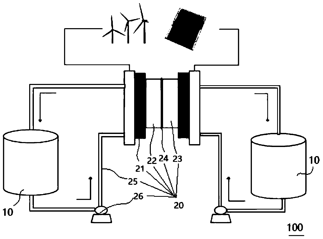
[0072] The negative electrode active material in the negative electrode electrolyte solution 23 is 0.05mol L -1 1,4-dihydroxyanthraquinone, the positive electrode active material in the positive electrode electrolyte solution 22 is 0.05mol L -1 4-OH-TEMPO, the supporting electrolyte in the positive electrolyte 22 and the negative electrolyte 23 are both 2.5mol L -1 Table 1 shows the coulombic efficiency, voltage efficiency and energy efficiency of the single cell of the salt cavern-based aqueous organic flow battery system (Ⅰ) assembled in the sodium chloride solution, and using NaOH to adjust the pH of the solution to 14.0.

Embodiment 2

[0074] The negative electrode active material in the negative electrode electrolyte solution 23 is 0.05mol L -1 1,4-dihydroxyanthraquinone, the positive electrode active material in the positive electrode electrolyte solution 22 is 0.05mol L -1 4-OH-TEMPO, the supporting electrolyte in the positive electrolyte 22 and the negative electrolyte 23 are both 2.5mol L -1 Table 1 shows the coulombic efficiency, voltage efficiency, and energy efficiency of the single cell of the salt cavern-based aqueous organic flow battery system (II) assembled using KOH to adjust the pH of the solution to 14.0.

Embodiment 3

[0076] The negative electrode active material in the negative electrode electrolyte solution 23 is 0.1mol L -1 1,4-dihydroxyanthraquinone, the positive electrode active material in the positive electrode electrolyte solution 22 is 0.1mol L -1 4-OH-TEMPO, the supporting electrolyte in the positive electrolyte 22 and the negative electrolyte 23 are both 2.5mol L -1 Sodium sulfate solution, using NaOH to adjust the pH of the solution to 14.0, the coulombic efficiency, voltage efficiency and energy efficiency of the single cell of the salt cave-based aqueous organic flow battery system (Ⅲ) assembled are shown in Table 1.


PUM

PropertyMeasurementUnit
pore sizeaaaaaaaaaa
pore sizeaaaaaaaaaa
thicknessaaaaaaaaaa

Abstract

The invention discloses an organic liquid flow battery system for an aqueous system based on a salt cavern. The organic liquid flow battery system comprises two electrolyte reservoirs and liquid flowbattery stacks, wherein the electrolyte reservoirs are salt caverns with physical cavities formed after the salt mine is mined, electrolytes are stored in the cavities and comprise a positive active material, a negative active material and a support electrolyte, the positive active material is a 2,2,6,6-tetramethylpiperidine oxynitride compound, the negative active material is anthraquinones, thepositive active material and the negative active material are directly dissolved or dispersed in a system in which water is used as a solvent in ontological form, the support electrolyte is dissolvedin the system; and the liquid flow battery stacks are respectively connected to the two electrolyte reservoirs. The organic liquid flow battery system for an aqueous system based on a salt cavern notonly has the advantages such as low cost, high safety performance, stable charge and discharge performance and high solubility of active materials, but also can solve large-scale electrochemical energy storage and make full use of some abandoned salt cavern resources.

Description

technical field [0001] The invention belongs to the field of liquid flow batteries, and in particular relates to an organic liquid flow battery system based on a salt cavern-based aqueous phase system, which can be applied to large-scale chemical energy storage. Background technique [0002] With the rapid development of the human economy, environmental pollution and energy shortages are becoming more and more serious, prompting countries all over the world to develop and utilize renewable energy such as wind energy, solar energy, and tidal energy. However, these renewable energy sources are discontinuous, unstable, restricted by regional environment, and difficult to connect to the grid, resulting in low utilization rate, high wind and light abandonment rate, and waste of resources. Therefore, it is necessary to vigorously develop efficient, cheap, safe and reliable energy storage technology that can be used in conjunction with it. [0003] Among various electrochemical en...

Claims


Application Information

Patent Timeline
Patent Type & Authority Applications(China)
IPC IPC(8): H01M8/04276H01M8/18
CPCH01M8/04283H01M8/188H01M2300/0002Y02E60/50
Inventor 徐俊辉韩俊甜崔耀星苏志俊李丹马旭强陈留平
Owner CHINASALT JINTAN
Why Eureka
Try Eureka