Treatment system for waste gas from plastic residues

A technology for waste gas treatment and slag, which is applied in the directions of air quality improvement, smoke removal, and dispersed particle separation. Threat of personal injury, good effect of collecting gas

Pending Publication Date: 2019-04-12
广东致顺化工环保设备有限公司
View PDF11 Cites 0 Cited by
  • Summary
  • Abstract
  • Description
  • Claims
  • Application Information

AI Technical Summary

Problems solved by technology

[0006] 2. In the process of using boilers to incinerate industrial waste residues, the temperature of most furnaces is between 300-500°C; a large amount of high-temperature water vapor and organic waste gases will be generated; industrial wastes are often mixed with waste textiles, artificial leather, wood chips, and oily dirt Substances, water, etc.; during the incineration process, more high-temperature acidic water vapor, organic waste gas, etc., and even dioxin gas will be produced
[0007] The treatment methods of such waste gas usually include: high-temperature incineration method, biofilm method, activated carbon adsorption method, etc.; especially the biofilm absorption method, the waste gas needs to be pre-treated before the treatment of the above-mentioned high-temperature water vapor, oil vapor, acid gas and other waste gases. Treatment, that is, cooling to 15-30°C; the existing condenser can only reduce the temperature, but cannot remove some harmful substances in the gas, and the cooling effect needs to be improved

Method used


Image

  • Treatment system for waste gas from plastic residues
  • Treatment system for waste gas from plastic residues
  • Treatment system for waste gas from plastic residues

Examples


Embodiment 1

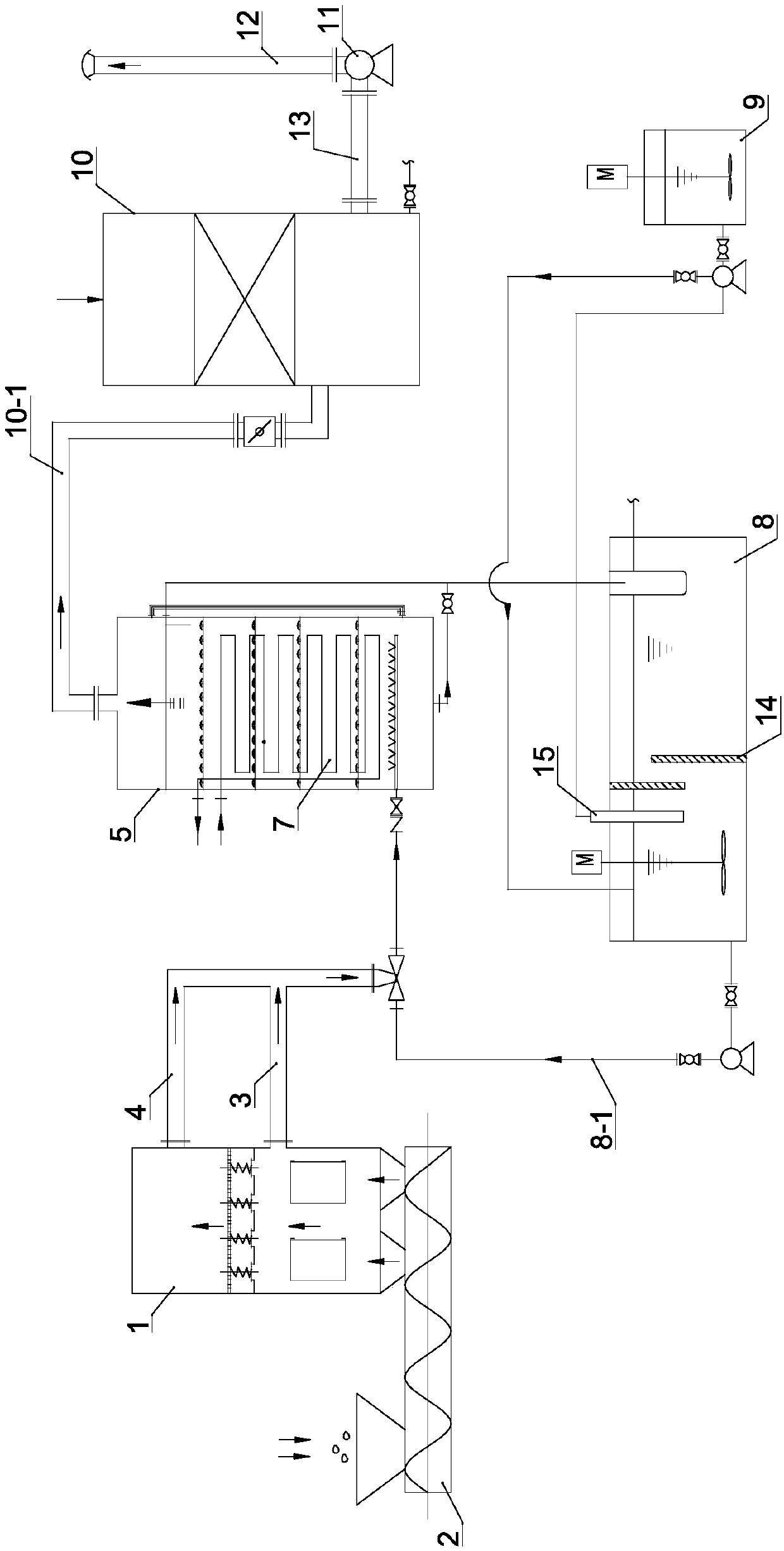
[0046] see figure 1 , a rubber slag waste gas treatment system of the present invention includes a gas collection module, a condensation pretreatment module for condensing and absorbing pretreatment of the collected waste gas, and a waste gas treatment for biological absorption treatment of the condensed and pretreated waste gas module.

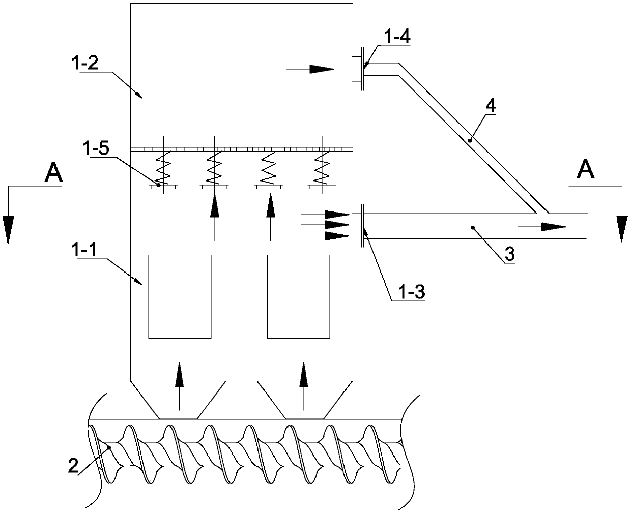
[0047] see figure 1 with 2 , the gas collection module includes an explosion relief gas collection hood 1, which is arranged above the exhaust port of the granulator 2, and includes a normal gas collection part 1-1 and a negative pressure explosion relief part 1- 2. The internal space of the normal gas collection part 1-1 is a gas collection and exhaust area, and the internal space of the negative pressure explosion relief part 1-2 is a negative pressure explosion relief area; the cover of the gas collection and exhaust area The wall is provided with a gas collection hood exhaust port 1-3, and the gas collection hood exhaust port 1-3 is co...

Embodiment 2

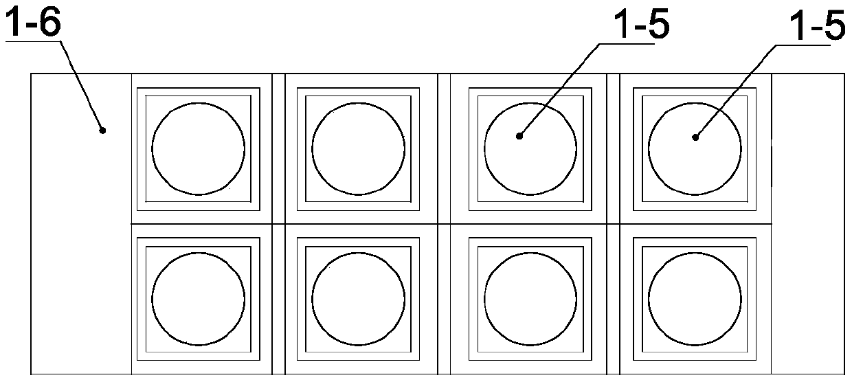
[0061] see Image 6 , The difference between this embodiment and Embodiment 1 is that the gas-gathering exhaust area and the negative pressure explosion relief area are separated by a partition plate 1-6, and the partition plate 1-6 is vertically arranged, divided into The area on one side of the partition 1-6 is the gas collection and exhaust area, and the area on the other side of the partition 1-6 is the negative pressure explosion relief area, and the explosion relief valve 1-5 is set on the partition 1-6 superior. When the explosion relief valve 1-5 is in the explosion relief state, the exhaust gas enters the negative pressure explosion relief area through the horizontal movement of the explosion relief valve 1-5, and then enters the first gas transmission main pipe 3 through the gas transmission branch pipe 4, thereby Realize exhaust gas venting task.

[0062] Refer to Embodiment 1 for implementation of other implementation modes other than the above in this embodiment...

Embodiment 3

[0064] see Figure 7 , The difference between this embodiment and Embodiment 1 is that the gas collection and exhaust area and the negative pressure explosion relief area are arranged in independent covers, and the corresponding covers of the gas collection and exhaust area and the negative pressure explosion relief area The bodies are connected through a large-diameter pipeline 1-7, and the explosion relief valve 1-5 is arranged in the large-diameter pipeline 1-7. When the explosion relief valve 1-5 is in the explosion relief state, the exhaust gas enters the cover corresponding to the negative pressure explosion relief area through the large-diameter pipeline 1-7, and then enters the first gas transmission main pipe 3 through the gas transmission branch pipe 4 , so as to realize the task of venting the exhaust gas.

[0065] Refer to Embodiment 1 for implementation of other implementation modes other than the above in this embodiment.


PUM


Abstract

The invention discloses a treatment system for waste gas from plastic residues. The treatment system comprises a gas collection module, a condensation pretreatment module and a waste gas treatment module, wherein the gas collection module comprises a venting and blasting gas collection hood which comprises a normal gas collection part and a negative-pressure venting and blasting part; the internalspace of the normal gas collection part is a gas collection and discharging part; the internal space of the negative-pressure venting and blasting part is a negative-pressure venting and blasting area; a normally-closed venting and blasting valve is arranged between the gas collection and discharging area and the negative-pressure venting and blasting area; the condensation pretreatment module comprises a multifunctional absorption condenser; the inner cavity of the multifunctional absorption condenser constitutes a condensation chamber; the lower end of the condensation chamber is provided with a waste gas inlet and a gas distribution pipe; the upper end of the condensation chamber is provided with a condenser exhaust outlet; and the waste gas treatment module comprises a waste gas treatment device, an induced draft device and a chimney. The treatment system for the waste gas from the plastic residues provided by the invention can guarantee the safety of a whole waste gas collectionsystem and can perform condensation and absorption pretreatment to the waste gas before performing concentrated treatment to the waste gas, so the treatment effect of the waste gas is improved.

Description

technical field [0001] The invention relates to an equipment waste gas treatment system, in particular to a rubber residue waste gas treatment system. Background technique [0002] In the process of industrial production and treatment such as waste plastic recycling and waste incineration, waste gas will be generated. In order to avoid direct discharge of it and cause air pollution, it is necessary to use waste gas collection devices and waste gas treatment devices in sequence before discharge. Collection and treatment of waste gas. [0003] For example, waste gas will be generated when "heating evaporation dehydration + granulation" is carried out on rubber residue, which needs to be collected and transported to the waste gas treatment device for treatment. Under normal circumstances, the exhaust gas collection device can smoothly and effectively collect the exhaust gas under the suction of the jet aspirator. When the tension of the molten plastic is exhausted in an explo...

Claims


Application Information

Patent Timeline
Patent Type & Authority Applications(China)
IPC IPC(8): B01D53/84B08B15/02
CPCB01D53/84B08B15/02Y02A50/20
Inventor 冯治平
Owner 广东致顺化工环保设备有限公司
Why Eureka
Try Eureka