
Feeding hydraulic system

A hydraulic system and hydraulic cylinder technology, applied in the direction of fluid pressure actuators, servo motors, servo motor components, etc., can solve the problem of difficulty in continuously releasing high-power drive energy, limited ability of hydraulic oil to store potential energy, and large flow of hydraulic oil, etc. Problems, to achieve the effect of reducing development and maintenance costs, large feed load, and high positioning accuracy

Pending Publication Date: 2019-04-12
中国空气动力研究与发展中心超高速空气动力研究所
View PDF0 Cites 0 Cited by
  • Summary
  • Abstract
  • Description
  • Claims
  • Application Information

AI Technical Summary

Problems solved by technology

However, from the basic characteristics of liquid incompressibility, it can be seen that the ability of hydraulic oil to store potential energy is limited, and it is difficult to continuously release high-power driving energy
Moreover, under the same pressure difference, if the single hydraulic cylinder scheme needs to ensure sufficient carrying capacity, the cylinder diameter needs to be increased, which makes the flow rate of hydraulic oil large at high feed speeds.

Method used


Image

  • Feeding hydraulic system

Examples


Embodiment 1

[0033] The working process of this embodiment is as follows:

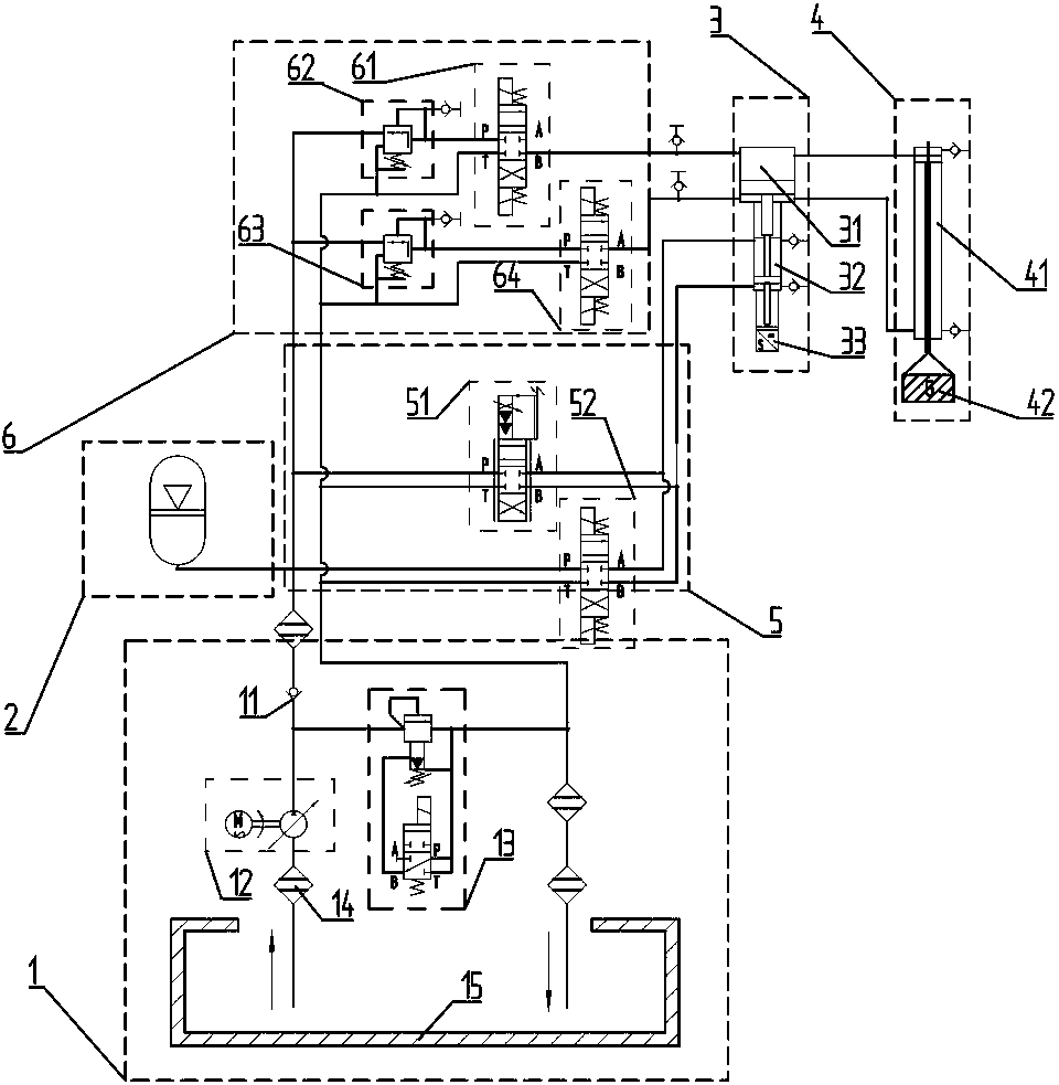
[0034] In the preparation stage, the hydraulic oil in the oil tank 15 is pressurized by the hydraulic pump 12 and sent to the high-pressure tank 2 through the check valve 11 to compress the nitrogen in the tank. The liquid level of the hydraulic oil in the tank rises, and the nitrogen is compressed to a predetermined value of 15MPa-30Mpa. Pressure; when the pressure is too high, the overflow valve 13 is opened to release the pressure, and the hydraulic pump 12 stops working.

[0035] During use, the high-pressure tank 2 forms a hydraulic circuit through the pipeline, the feeding and lifting pipeline valve assembly 5 and the servo control and proportional increasing hydraulic cylinder 3 . When the load 42 needs to be quickly sent to the flow field, the servo flow valve 51 in the feed and lift pipeline valve assembly 5 is opened, and the high-pressure hydraulic oil enters the servo-controlled and proportional speed-u...

Embodiment 2

[0040] The implementation mode of this embodiment is basically the same as that of Embodiment 1, the main difference is:

[0041] During the factory commissioning of the equipment and the function recovery commissioning after the equipment maintenance, the high-pressure tank 2, the equipment commissioning pipeline valve assembly 6, the servo control and proportional increase hydraulic cylinder 3 and the fast execution hydraulic cylinder 41 form a commissioning loop. Its function is to remove the air in the hydraulic pipeline and hydraulic cylinder, and to determine the initial position of the hydraulic cylinder piston. The device initialization is realized through the upper layer control software, which plays an important role in the factory commissioning of the device and the function recovery after the overhaul of the device.


PUM


Abstract

The invention discloses a feeding hydraulic system. The feeding hydraulic system is a triple cylinder hydraulic servo system using a high pressure nitrogen source as the driving source in the feedingprocess. The feeding hydraulic system uses the high pressure nitrogen to drive the hydraulic oil, and a hydraulic cylinder is driven by the hydraulic oil to be fed quickly. The feeding hydraulic system uses a displacement sensor as the feedback source to form the closed-loop control and realize the precise positioning. The equipment debugging pipeline valve assembly in the feeding hydraulic systemrealizes the positioning function of initial positions of a hydraulic pipeline, automatic exhaust of the hydraulic cylinder and a cylinder body. The feeding hydraulic system has the characteristics of being high in feeding load, high in speed and high in positioning accuracy. The feeding hydraulic system reduces the performance requirement of a hydraulic pump and is helpful to reduce the development and maintenance cost. The feeding hydraulic system can quickly and smoothly feed a wind tunnel test model and accurately position the wind tunnel test model in a wind tunnel test section, and thewide application value is achieved in the study of the pneumatic thermal test of a wind tunnel.

Description

technical field [0001] The invention belongs to the field of hydraulic servo drive and control, in particular to a feeding hydraulic system. Background technique [0002] When carrying out the aerothermal test of the aircraft model, it is usually necessary to quickly and smoothly deliver the test model located outside the flow field into the test airflow. The structural members supporting the model and all moving parts such as the model weigh hundreds of kilograms. The feeding equipment needs to send the model into the core area of ​​the flow field within a feeding time of about 0.3 seconds, with a stroke of about 1 meter. Due to factors such as oil pollution, dust, high vacuum, and strong electromagnetic interference in the test environment, the use of a hydraulic system as a power source has been used by many wind tunnels in China because of its higher reliability and lower maintenance costs. [0003] Among similar wind tunnel equipment in China, the scheme driven by sin...

Claims


Application Information

Patent Timeline
Patent Type & Authority Applications(China)
IPC IPC(8): F15B11/08F15B13/02F15B13/04
CPCF15B11/08F15B13/021F15B13/025F15B13/04
Inventor 皮兴才李绪国邱华诚闵夫乔永强
Owner 中国空气动力研究与发展中心超高速空气动力研究所
Learn More