Phase change heat dissipation device

A technology for heat dissipation device and phase change heat, which is used in indirect heat exchangers, lighting and heating equipment, cooling/ventilation/heating renovation, etc. Non-uniformity and other problems, to achieve the effect of improving pressure bearing capacity, efficient boiling heat transfer, and uniform heat expansion

Pending Publication Date: 2019-04-12
ZHUZHOU ZHIRE TECH
View PDF7 Cites 9 Cited by
  • Summary
  • Abstract
  • Description
  • Claims
  • Application Information

AI Technical Summary

Problems solved by technology

[0005] Since the heat pipe itself is tubular, and the number of heat pipes suitable for a heat pipe radiator is very limited, the direct contact area between the heat pipe and the heat source is not large, so there will be great obstacles when the heat is transferred from the heat source to the phase change component (heat pipe). The thermal efficiency is not high, the heat dissipation performance is severely limited, and it can also cause local high temperature of the base
In addition, the heat dissipation method of the heat pipe is one-dimensional, which conducts heat in a linear manner. The heat dissipation capacity and heat dissipation effect of the heat pipe itself are not optimal, and the cost of processing the heat pipe radiator is also high. For most phase change radiators, most It works in an internal vacuum environment, which restricts the flow of the internal phase-change heat medium, which is not conducive to heat dissipation
[0006] In addition, the current heat pipe shell material is mostly copper, while the base material is mostly aluminum alloy. Usually, low-temperature tin brazing or cementing is used to fill the gap between the heat pipe and the base after forming, which will generate a certain thermal resistance, which is not conducive to heat transfer. The disadvantages of low-temperature tin-lead soldering include: the overall surface treatment of the radiator, such as nickel plating or copper plating, must be carried out before soldering. The welding and surface treatment lead to high costs and pollution to the environment; tin soldering is difficult to ensure that the heat pipe The plane filling with the aluminum alloy base is very good, and there is no local gap, but because the heat pipe is under the power device, the heat flux density is high, and the gap will cause the local temperature rise of the heat source device, resulting in device loss
The processing cost of the heat pipe radiator is high, and there is pollution to the environment
[0007] Therefore, the traditional phase change radiator has problems such as large heat transfer resistance, uneven heat transfer, high production cost and low heat transfer efficiency.

Method used


Image

  • Phase change heat dissipation device
  • Phase change heat dissipation device
  • Phase change heat dissipation device

Examples


Embodiment 1

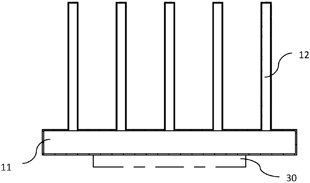
[0081] For the heat source 30 with a size of 30mm×45mm, the power of the heat source 30 is adjusted by frequency conversion, the condensing part 12 is air-cooled, the air volume is provided by the test wind tunnel, the inlet air temperature is 25°C, and the outlet air temperature is 50°C. Control the temperature at 60°C, use different phases to change the heat medium 20, and test the working pressure and heating power inside the phase change component. The test results are shown in Table 2:

[0082] Table 2

[0083]

[0084] As can be seen from the data in Table 2, the present invention uses a phase-change heat medium 20 with a boiling point lower than 30° C. under standard atmospheric pressure. Due to the increase in the pressure difference in the phase-change component, the transmission capacity of the phase-change component is greatly increased. For a size of 45mm ×69mm CPU, radiator with the same volume, using R134a, R142b, R114, R124, R1233Zd(E), R1234Ze(Z), R1234Ze(E)...


PUM


Abstract

The invention discloses a phase change heat dissipation device which comprises a phase change component, wherein a phase change heat exchange medium is arranged in the phase change component, when thephase change heat exchange medium arranged in the phase change component is configured to a work state of the phase change heat dissipation device, the atmospheric pressure in the phase change component is more than 0.15MPa. When the phase change heat dissipation device is at work, the work temperature range is 30-80 DEG C, internal pressure is far larger than a standard atmospheric pressure, under a positive pressure non-vacuum environment, heat-flow density of a heating source is large, absolute pressure of a phase change component evaporation part is high, relative pressure difference of different parts of the phase change component under the same temperature difference condition is large, and more phase change mediums can be driven by the pressure difference so as to reinforce the heat exchange ability. With adoption of the phase change heat dissipation device, the mobility of the internal phase change heat exchange medium is improved, the heat-flow density of heat transfer is improved, and efficient heat dissipation is easily realized.

Description

technical field [0001] The invention belongs to the technical field of phase-change heat dissipation devices, in particular to a phase-change heat dissipation device for electronic devices. Background technique [0002] Phase change heat dissipation is an efficient heat dissipation method. Its principle is to use the phase change heat medium to boil and gasify at a certain temperature to absorb heat, and then the gasified gas is condensed and liquefied at other locations to release heat, thereby realizing heat transfer. It has good heat transfer effect and wide application. [0003] At present, phase change radiators generally use heat pipes for phase change heat dissipation. Compared with other traditional heat dissipation methods, the heat transfer efficiency of heat pipe heat dissipation is high, and the heat dissipation effect is good. Common heat pipe radiators are mainly composed of three parts, namely heat pipes, heat dissipation fins, and heat conduction bases. The...

Claims


Application Information

Patent Timeline
Patent Type & Authority Applications(China)
IPC IPC(8): F28D15/02
CPCF28D15/02F28D15/0266F28D15/0233F28D15/025F28D2021/0029H05K7/20309H05K7/20318H05K7/20336
Inventor 李纯胡广帆姚春红马秋成
Owner ZHUZHOU ZHIRE TECH
Why Eureka
Try Eureka