decorative film

A decorative film and film stack technology, applied in mirrors, instruments, optics, etc., can solve the problems of poor decorative effects of multi-layer optical films, and achieve the effect of highlighting the decorative effect of recognition, bright and sharp colors, and highlighting the decorative effect

Active Publication Date: 2021-10-26
ZHANGJIAGANG KANGDE XIN OPTRONICS MATERIAL
View PDF22 Cites 0 Cited by
  • Summary
  • Abstract
  • Description
  • Claims
  • Application Information

AI Technical Summary

Problems solved by technology

[0004] The main purpose of the present invention is to provide a decorative film to solve the problem of poor decorative effect of multilayer optical films in the prior art

Method used


Image

  • decorative film
  • decorative film
  • decorative film

Examples


Embodiment 1

[0082] Simulation experiment data:

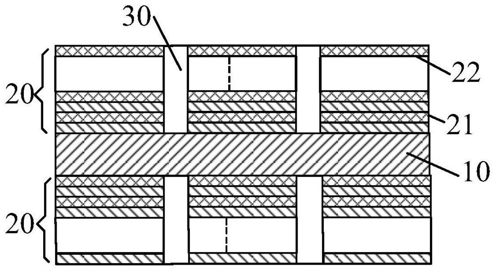
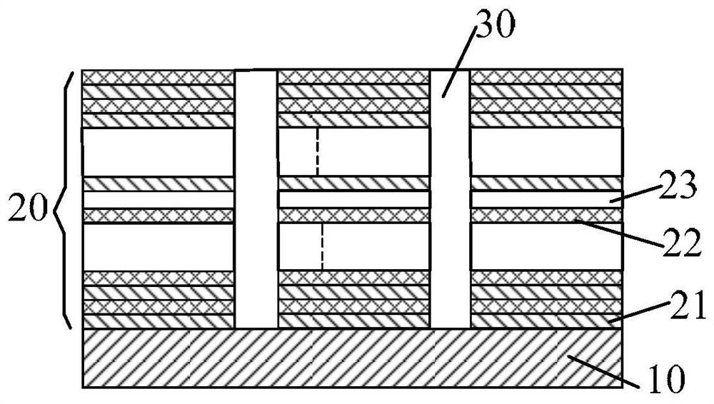
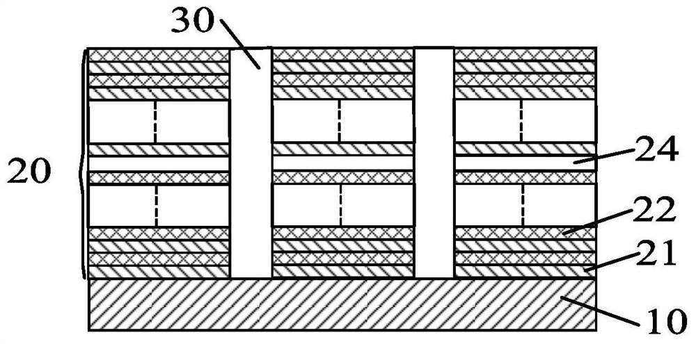
[0083] A PET layer with a thickness of 0.05 mm is used as the transparent substrate layer. On the PET layer, an anti-reflection layer and a film stack of reflective film system (high refractive index material layer and low refractive index material layer are cross-stacked), wherein the shape pattern of the film stack is set to be a landscape pattern, and the film stack The hollowed-out gaps are filled with PET, the central wavelength of the incident light is set to 532nm, the high refractive index material layer is a titanium dioxide layer with a refractive index of 2.354, and the low refractive index material layer is a silicon dioxide layer with a refractive index of 1.46. The transparent layer is composed of a titanium dioxide layer and a silicon dioxide layer with an optical thickness of λ / 4, and the optical thickness coefficient of the reflective film system is designed as:

[0084] 第一半膜堆:0.216H 1.836L 0.303H 1.691L 0.377H 1.591L 0.56...

Embodiment 2

[0089] The two half-film stacks of the decorative film corresponding to Example 1 were fabricated by using the magnetron sputtering process, and the substrate was cleaned with a clean cloth and ethanol. Design the mask plate with the void as "landscape pattern".

[0090] After degassing the vacuum chamber, use a vacuum cleaner to clean the inside of the bell jar, fill the molybdenum boat with the film material to be evaporated, and record the name of the film material of each boat. And place the substrate on the substrate frame, do not tilt the substrate, and place the mask plate on the cleaned substrate. Drop the bell jar and evacuate the vacuum chamber according to the operation rules of the coating machine. When the vacuum reaches 7×10 -3 After Pa, pre-melt the film material in the molybdenum boat in turn to remove the gas in the film material. At this time, pay attention to block the film material with a baffle to ensure that the substrate will not be plated during pre-...

Embodiment 3

[0093] Simulation experiment data:

[0094] The optical thickness coefficient of the high-refractive index material layer and the optical thickness coefficient of the low-refractive index material layer of the film system are the same as in Example 1, and the two half-film stacks are arranged on two opposite surfaces of the PET layer. Use the Essential Macleod film system design software to simulate the light reflection performance of the above-mentioned decorative film, and the simulation results are shown in Figure 7 and Table 1.


PUM

PropertyMeasurementUnit
thicknessaaaaaaaaaa
thicknessaaaaaaaaaa
thicknessaaaaaaaaaa

Abstract

The invention provides a decorative film. The reflective film system of the decorative film includes a hollow refraction material part, and the refraction material part includes at least one film structure of │(α 1 Hβ 1 Lα 2 Hβ 2 L...α m Hβ m L)│ film stack, where H represents a high refractive index material layer, L represents a low refractive index material layer, n and m are positive integers, and 3<n≤150, 3<m≤50, m≤n, same α in a stack 1 , α 2 ,...,α m and beta m ,...,β 2 , β 1 Each independently satisfies the same gradient law on the same cosine waveform or sine waveform; for the i-th high and low refractive index material unit α i Hβ i L, 1≤i≤n,α i Indicates that the optical thickness of the i-th high refractive index material layer accounts for a multiple of λ / 4, β i Indicates that the optical thickness of the i-th low refractive index material layer accounts for a multiple of λ / 4, and λ is the monitoring wavelength of the film stack. The color of the pattern displayed by the refraction material portion of the decorative film is sharp.

Description

technical field [0001] The invention relates to the field of optical film structures, in particular to a decorative film. Background technique [0002] In-mold decoration molding technology is widely used in appearance parts such as electronic products, home appliances, automobiles and motorcycles. When the known in-mold decoration molding technology is used to make a mirror or color-changing effect with a dazzling shell, it must be coated with a layer on the surface of the substrate or multi-layer metal or pigment layers, and if it is necessary to achieve the effect of changing different colors according to different viewing angles, it is necessary to use multi-layer evaporation to make it, but the ductility of the metal coating formed by evaporation is poor, making the in-mold decoration The qualification rate of the molding process is low, and the overall product quality cannot be improved. [0003] In order to solve the above-mentioned defects of the metal coating, the ...

Claims


Application Information

Patent Timeline
Patent Type & Authority Patents(China)
IPC IPC(8): G02B5/08G02B1/10
CPCG02B1/10G02B5/0816
Inventor 于甄张国臻夏振
Owner ZHANGJIAGANG KANGDE XIN OPTRONICS MATERIAL
Why Eureka
Try Eureka