Boiler smoke exhaust purification system

A purification system and boiler technology, applied in chemical instruments and methods, separation methods, dispersed particle separation, etc., can solve problems such as insufficient contact between gas and desulfurization slurry, increased workload and maintenance costs, and failure to achieve desulfurization and dust removal effects. , to achieve the effect of good desulfurization and denitrification, prevention of secondary pollution, and thorough purification of exhaust gas

Inactive Publication Date: 2019-04-16
河南省锅炉压力容器安全检测研究院
View PDF1 Cites 0 Cited by
  • Summary
  • Abstract
  • Description
  • Claims
  • Application Information

AI Technical Summary

Problems solved by technology

The turbulent flow dedusting and desulfurization equipment with this structure mixes the dust particles contained in the soot, lye, and sulfur-containing and nitrogen-containing airflow. The dust particles are easy to adhere to the reaction layer, causing silting and clogging, which affects the continuous operation of the equipment, and requires regular cleaning. The spherical layer increases the workload and maintenance cost. After continuous use, in the desulfurization and dust collector, the contact between the gas and the desulfurization slurry is not good enough, so the ideal desulfurization and dust removal effect cannot be achieved.

Method used


Image

  • Boiler smoke exhaust purification system
  • Boiler smoke exhaust purification system
  • Boiler smoke exhaust purification system

Examples


Embodiment 1

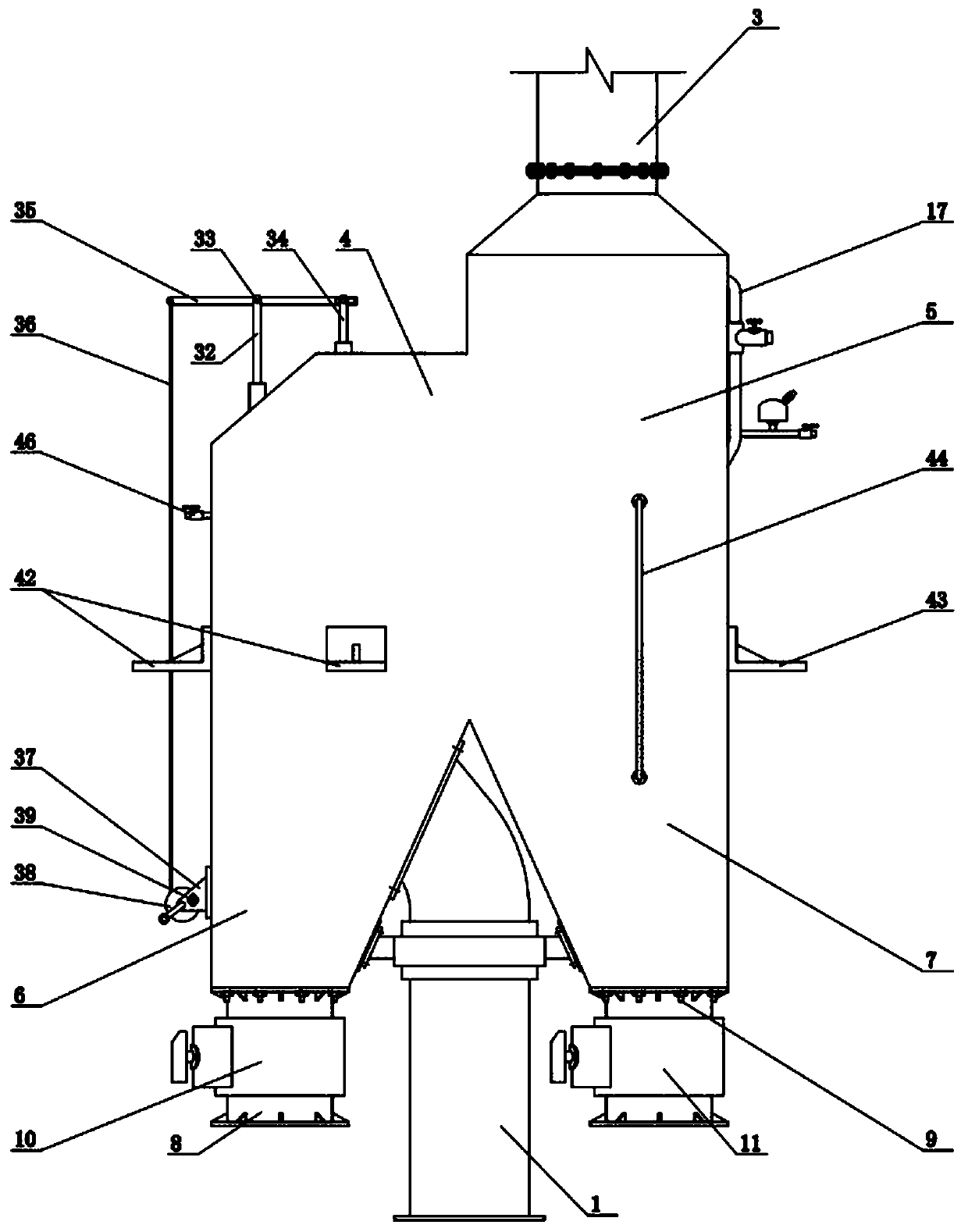
[0022] Embodiment 1: as figure 1 The shown boiler exhaust purification system, its main body includes a dust removal chamber 4 and a desulfurization and denitrification chamber 5, the dust removal chamber bracket 42 and the desulfurization and denitrification chamber bracket 43 are arranged on both sides of the main body, and are fixed and installed on the boiler chimney 3 through the brackets 37 on both sides. The fixed frame (fixed frame is not shown in the figure) provided on both sides of the exhaust outlet of the boiler, wherein the smoke inlet joint 1 is connected to the exhaust outlet of the boiler, the outlet of the silt discharge channel 8 and the outlet of the sewage discharge channel 9 are respectively connected to the silt discharge pipe Sealed with the sewage pipe. The whole system is easy to install. After installation, add water to the dedusting chamber 4 and add alkali to the desulfurization and denitrification chamber 5, and adjust the height of the air pressu...

Embodiment 2

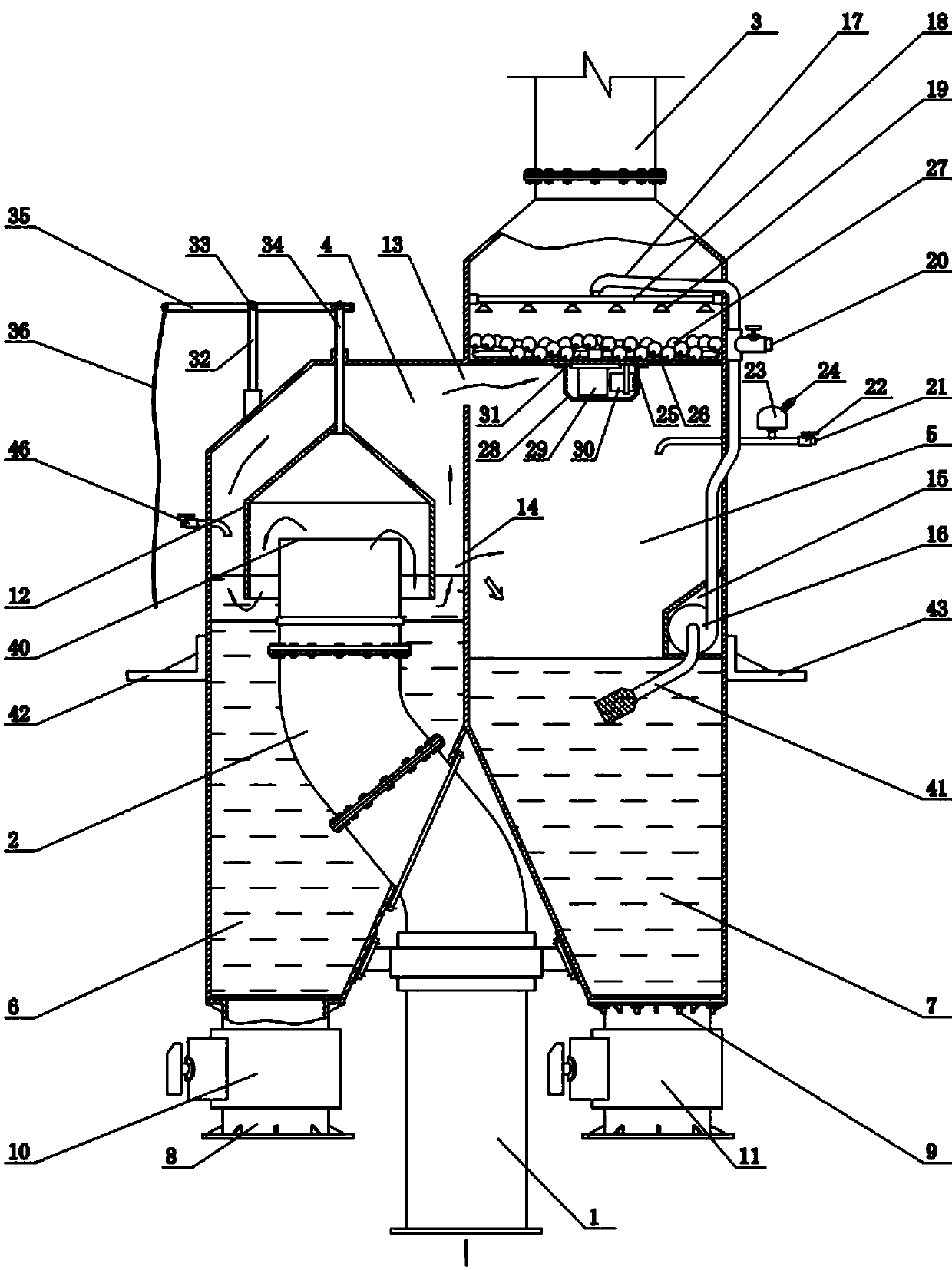
[0028] Embodiment 2: On the basis of Embodiment 1, the similarities will not be repeated. The difference is that a smoke washing mechanism is arranged in the desulfurization and denitrification chamber 5, which is the upper part of the desulfurization and denitrification chamber 5 and the lye spraying mechanism The lower part is provided with a flat carrier plate 25, and there is an annular mesh layer 26 around the flat carrier plate 25, and a layer of smoke washing balls 27 is laid on the upper side of the flat carrier plate 25 and the annular mesh layer 26. The smoke washing mechanism also includes a smoke washing ball 27 stirring mechanism, a sealing cover 28 is fixed below the flat carrier plate 25, a gearbox 29 and a motor 30 are fixed in the sealing cover 28, the input end of the gearbox 29 is connected with the rotating shaft of the motor 30, and the gearbox 29 After the output end vertically passes through the central hole provided by the flat carrier plate 25, a stirri...

Embodiment 3

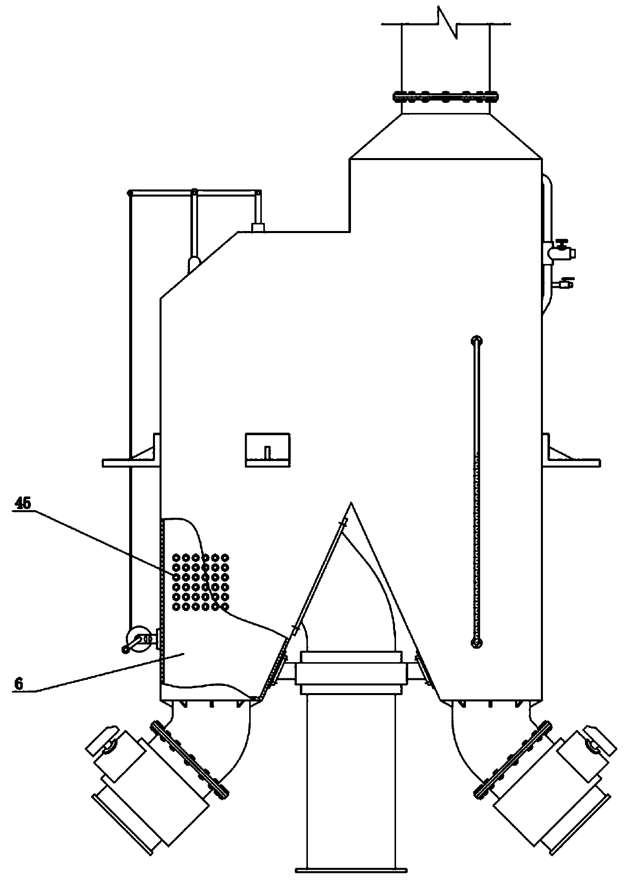
[0030] Embodiment 3: On the basis of Embodiment 1, the similarities are not repeated, and the difference is that the present embodiment adopts such as image 3 As shown, a heat exchange structure is set in the dust removal chamber 4, and a plurality of heat exchange pipes 45 run through the dust removal chamber 4, which can be used to heat the boiler inlet water. The output passes through to preheat the cold water, or preheat the boiler inlet, and reuse the heat energy discharged from the chimney.


PUM


Abstract

The invention discloses a boiler smoke exhaust purification system, which includes a dust removal chamber and a desulfurization and denitrification chamber. The upper part between the dust removal chamber and the desulfurization and denitrification chamber communicates through a smoke exhaust channel, and the middle between the dust removal chamber and the desulfurization and denitrification chamber communicates through an overflow channel; and the upper part of the dust removal chamber is provided with a water supplying pipe, the liquid level in the dust removal chamber is maintained to be located on the position of an overflow channel opening, the liquid level in the desulfurization and denitrification chamber is maintained to be not higher than the position of the overflow channel opening, and the upper part of the desulfurization and denitrification chamber is provided with a lye supplying pipe. According to the boiler smoke exhaust purification system, dust removal and desulfurization and denitrification are conducted separately, and the problems that lye waste due to the fact that dust contaminates lye and precipitation is difficult to handle can be solved; and dust depositions are cleared independently through the dust removal chamber, the desulfurization and denitrification chamber is used for discharging reactive sediments independently, and different effluents are handled correspondingly, so that the action of efficient handling and secondary pollution prevention is achieved.

Description

technical field [0001] The invention belongs to the technical field of boiler exhaust gas purification equipment, and in particular relates to a boiler exhaust gas purification system capable of separating and treating smoke dust, desulfurization and denitrification. Background technique [0002] Smoke and sulfur dioxide emitted by industrial boilers are one of the largest sources of air pollution. Common flue gas desulfurization and dust removal devices for coal-fired boilers include spray type, Venturi tube type, impact purification type, etc. In order to improve the efficiency of dust removal, people usually use them in series or refit them, but often make the floor area or The production cost is greatly increased. The more common desulfurization and dust collectors used for boiler exhaust are generally wet desulfurization and dust collectors. The advantage of wet dedusting is that it is easy to maintain, and can achieve dust removal and desulfurization (denitrification...

Claims


Application Information

Patent Timeline
Patent Type & Authority Applications(China)
IPC IPC(8): F23J15/02F23J15/04B01D53/78B01D53/60
CPCB01D53/60B01D53/78F23J15/022F23J15/04
Inventor 王凤琴
Owner 河南省锅炉压力容器安全检测研究院
Why Eureka
Try Eureka