A High Energy Density Flat Carbon Electrode
A high-energy-density, carbon-electrode technology, applied in the direction of hybrid capacitor electrodes, circuits, capacitors, etc., can solve the problems of limited plate thickness, large proportion of current collector mass, large equivalent series resistance, etc., to reduce internal resistance , Good bonding effect, enhanced contact effect
- Summary
- Abstract
- Description
- Claims
- Application Information
AI Technical Summary
Problems solved by technology
Method used
Image
Examples
Embodiment 1
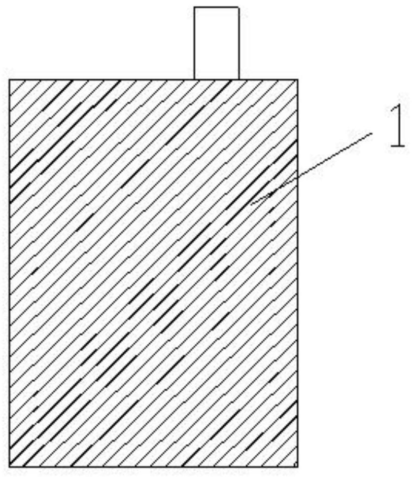
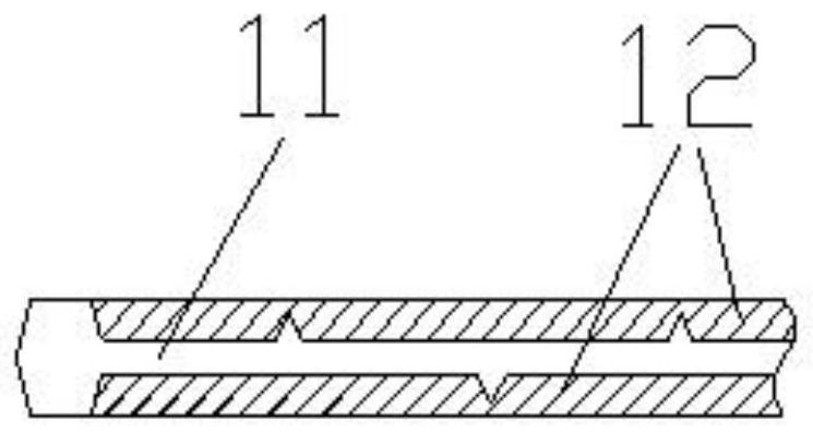
[0037] Example 1: Combining figure 1 , shown in Fig. 2, the flat carbon electrode 1 of the high energy density of the present embodiment, size is 68mm long, wide 44mm, thick 2.90mm, is in the flat lead current collector 11 that size is 66mm long, wide 42mm, thick 0.60mm Both sides are prepared by pressing the powder electrode layer 12, and the thickness of the prepared electrode plate is 2.90 mm.
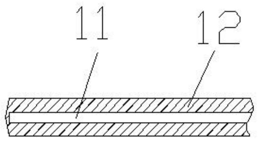
[0038] combine image 3 As shown, the powder electrode layer 12 in this embodiment is composed of a three-dimensional conductive network 121 and a negative active material 122; the negative active material 122 is composed of activated carbon, a conductive agent and a water-based binder; the three-dimensional The conductive network 121 is composed of an organic conductive binder that is in a different phase from the negative active material 122. During the mixing process, it is gradually drawn into filaments with the volatilization of the diluent, and finally adheres to each other d...
Embodiment 2
[0048] Embodiment 2: The difference between this embodiment and Embodiment 1 is: the weight ratio of the various material components of the powder electrode layer 12 is as follows: a, the mass percentage of the negative electrode active material and the three-dimensional conductive network, the negative electrode Active material 65%, three-dimensional conductive network 35%; b negative electrode active material, composed of activated carbon powder 80%, graphite powder 14%, PTFE emulsion (solid content 70%) 6%; c, three-dimensional conductive network, is composed of conductive agent and An organic conductive binder composed of an organic binder has a proportion of 25% conductive agent and 75% organic binder; the conductive agent is a mixture of 10% expanded graphite and 15% acetylene black; The organic adhesive is a mixture of 40% polyurethane resin and 35% epoxy resin.
[0049] All the other are with embodiment 1.
Embodiment 3
[0050] Embodiment 3: The difference between this embodiment and Embodiment 1 is: the weight ratio of the various material components of the powder electrode layer 12 is as follows: a, the mass percentage of the negative electrode active material and the three-dimensional conductive network, the negative electrode Active material 90%, three-dimensional conductive network 10%; b negative electrode active material, composed of activated carbon powder 85%, expanded graphite 9%, PTFE emulsion (solid content 70%) 4% and CMC 2%; c, three-dimensional conductive network, composed of 70% of fluorine rubber, 20% of graphite powder and 10% of acetylene black are prepared as a conductive adhesive, and the diluent is butyl acetate.
[0051] The organic-based conductive adhesive is composed of a conductive agent and an organic-based adhesive, and the weight percentages of each component are: 15% of a conductive agent, and 85% of an organic-based adhesive; wherein the conductive agent is carbo...
PUM
| Property | Measurement | Unit |
|---|---|---|
| thickness | aaaaa | aaaaa |
| thickness | aaaaa | aaaaa |
| particle size | aaaaa | aaaaa |
Abstract
Description
Claims
Application Information
 - R&D
- Intellectual Property
- Life Sciences
- Materials
- Tech Scout
- Unparalleled Data Quality
- Higher Quality Content
- 60% Fewer Hallucinations
Browse by: Latest US Patents, China's latest patents, Technical Efficacy Thesaurus, Application Domain, Technology Topic, Popular Technical Reports.
© 2025 PatSnap. All rights reserved.Legal|Privacy policy|Modern Slavery Act Transparency Statement|Sitemap|About US| Contact US: help@patsnap.com


