
High-gain operational amplifier using feedforward compensation

An operational amplifier and feed-forward compensation technology, which is applied to DC-coupled DC amplifiers, differential amplifiers, improved amplifiers to expand bandwidth, etc., can solve the problem of power supply rejection ratio reduction, increased chip area and power consumption, and difficult zero-pole offset, etc. Problems, to achieve high power supply rejection ratio, chip area reduction, and increase the effect of gain

Pending Publication Date: 2019-04-23
佛山臻智微芯科技有限公司
View PDF6 Cites 2 Cited by
  • Summary
  • Abstract
  • Description
  • Claims
  • Application Information

AI Technical Summary

Problems solved by technology

[0005] The current technical disadvantages of frequency compensation are: (1) Using Miller capacitance compensation to calculate the distribution of zero and pole points can accurately predict the frequency of the host point, but it cannot effectively predict the frequency of the zero point and the sub-pole of the circuit. Difficult to guarantee complete cancellation of pole-zero
(2) Due to the introduction of capacitors, the area and power consumption of the chip will be greatly increased. At the same time, because the capacitors push the main pole lower, the unity gain bandwidth product will be reduced.
The technical disadvantages of the existing two-stage op amp are: (1) the current gain of the two-stage op amp circuit is not large enough due to the performance; (2) the limited bandwidth caused by the inability to control the high-order poles in the circuit; (3) due to The reduction of power supply rejection ratio caused by traditional Miller compensation

Method used


Image

  • High-gain operational amplifier using feedforward compensation
  • High-gain operational amplifier using feedforward compensation
  • High-gain operational amplifier using feedforward compensation

Examples


Embodiment Construction

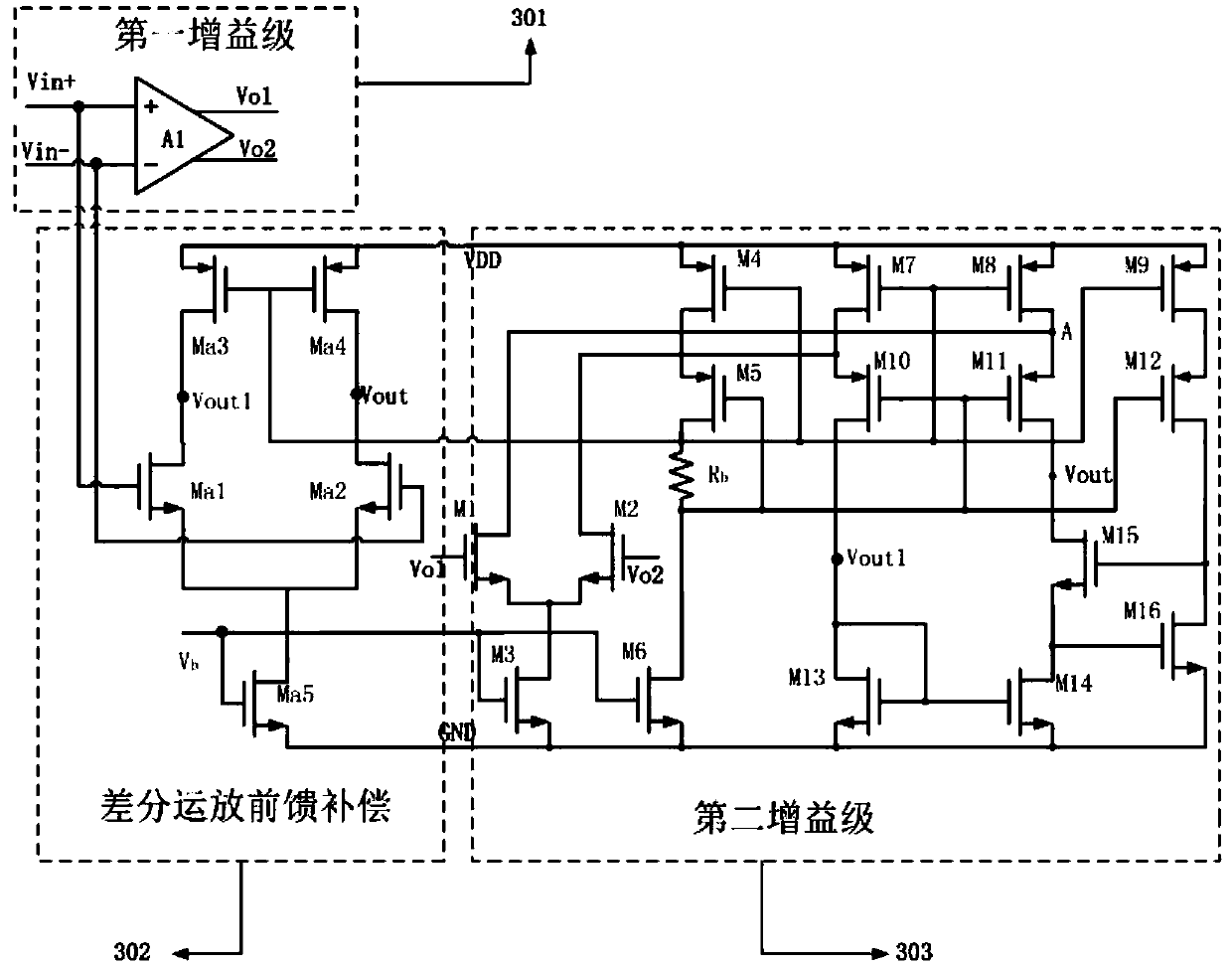
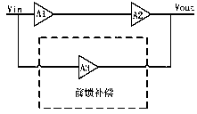
[0015] like figure 2 A high-gain operational amplifier designed by the present invention that uses feedforward compensation includes a differential first gain stage, a gain bootstrap cascode second gain stage and a differential pair feedforward compensation circuit.

[0016] The forward input terminal and the reverse input terminal of the first differential gain stage input the required signal, on the other hand, the positive input terminal and the reverse input terminal of the first differential gain stage are respectively connected to the feedforward The input ends of both ends of the compensation circuit; the output ends of the first differential gain stage are respectively connected to the input ends of the second gain stage. The first gain stage increases a part of the overall gain of the circuit.

[0017] The second gain stage of the gain bootstrap cascode structure, its input terminals are respectively connected to the output terminals of the first gain stage; the ou...


PUM


Abstract

The invention discloses a high-gain operational amplifier using feedforward compensation, comprising a differential first gain stage, a gain bootstrap type folded cascode second gain stage and a differential pair type feedforward compensation circuit; wherein the differential first gain stage and the gain bootstrap type folded cascode second gain stage are connected in series, and meanwhile the differential pair type feedforward compensation circuit is connected with the first and second gain stages in parallel. The feedforward compensation circuit adopts a differential pair type compensationcircuit, which is simple in structure, is easy to implement, and replaces the traditional compensation capacitor form, so that the chip area can be reduced, the feedforward compensation circuit is easy to be integrated, on the other hand, the feedforward compensation circuit replaces the traditional pole separation miller compensation technology to ensure circuit stability and to greatly increasethe bandwidth of the system at the same time; and the second gain stage adopts an error amplifier of a gain bootstrap type folded cascode structure, which can have a better power supply rejection ratio than the traditional differential circuit while meeting high gain, and a main pole is from a secondary pole due to the increase of the output resistance, so that the circuit is more stable.

Description

technical field [0001] The invention relates to a high-gain operational amplifier using feed-forward compensation. Background technique [0002] With the development of integrated circuit technology, the continuous improvement of integration, and the widespread use of digital-analog hybrid systems in the field of electronic information systems, the industry has put forward higher requirements for the design of analog integrated circuits: high performance, high integration, low power consumption etc. As an indispensable module unit in the analog and digital-analog hybrid system, the performance of the operational amplifier is directly related to the performance of the whole system. Therefore, the research and design of high-performance operational amplifiers are of great significance. On the one hand, the commonly used two-stage op amp contains many poles, which can easily lead to phase shift, that is, before the magnitude of the amplitude-frequency curve of the circuit dro...

Claims


Application Information

Patent Timeline
Patent Type & Authority Applications(China)
IPC IPC(8): H03F3/45H03F1/42
CPCH03F1/42H03F3/45
Inventor 周盼李思臻章国豪
Owner 佛山臻智微芯科技有限公司
Learn More