
An ultra-broadband wave-absorbing structure compatible with temperature resistance and mechanical properties and its preparation method

An ultra-broadband, wave structure technology, applied in chemical instruments and methods, transportation and packaging, layered products, etc., can solve problems such as inability to use high-speed flight environments, poor ultra-low frequency stealth performance, etc. The effect of strong design and high working temperature

Active Publication Date: 2021-11-30
BEIJING RES INST OF MECHANICAL & ELECTRICAL TECH
View PDF6 Cites 0 Cited by
  • Summary
  • Abstract
  • Description
  • Claims
  • Application Information

AI Technical Summary

Problems solved by technology

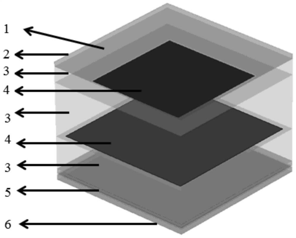
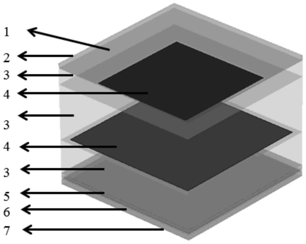
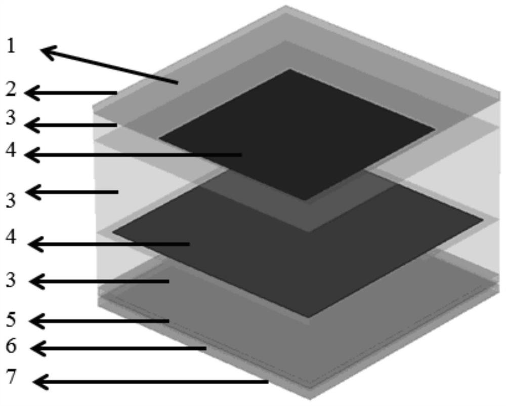
[0007] In order to solve the problem that the conventional wave-absorbing structure stealth scheme cannot be applied to the high-speed flight environment and the low-frequency stealth performance of the electric loss type high-temperature resistant wave-absorbing material or metamaterial is poor, the present invention proposes a high-speed flight environment that can be compatible with temperature-resistant Performance and mechanical properties of ultra-broadband absorbing structure

Method used


Image

  • An ultra-broadband wave-absorbing structure compatible with temperature resistance and mechanical properties and its preparation method
  • An ultra-broadband wave-absorbing structure compatible with temperature resistance and mechanical properties and its preparation method
  • An ultra-broadband wave-absorbing structure compatible with temperature resistance and mechanical properties and its preparation method

Examples


Embodiment 1

[0042] Step 1: Prepare the electromagnetic shielding layer

[0043] Two-dimensional laminated shielding SiC fibers (the real part of the dielectric constant is >20) are selected as the prefabricated body of the electromagnetic shielding layer, and the rough blank is prepared by the fiber impregnation and pyrolysis process (PIP). After the braid has sufficient strength and toughness, pass The electromagnetic shielding layer is obtained by machining.

[0044] Step 2: Prepare the magnetic wave-absorbing patch layer

[0045] Pour vulcanized polyurethane rubber and micron magnetic iron powder (60wt.%) into an open mill and knead evenly. The kneading temperature is 25°C-60°C, and the above-mentioned mixture is pressed into a wave-absorbing layer with a thickness of 0.3-3mm by a calender. Raw film, cut into the designed shape, put it into the mold, heat up and vulcanize after closing the mold, and obtain the required magnetic wave-absorbing patch material, its dielectric constant an...

Embodiment 2

[0057] Step 1: Prepare the electromagnetic shielding layer

[0058] The two-dimensional laminated T300 carbon fiber (conductivity is about 40000S / m) is selected as the prefabricated body of the electromagnetic shielding layer. After the braid has sufficient strength and toughness, the electromagnetic shielding layer is obtained by machining.

[0059] Step 2: Prepare precursors containing magnetic absorbers

[0060] Using micron magnetic iron-nickel alloy powder (75wt.%) as the wave absorbing agent and silica sol as the solvent, the wave absorbing agent and the solvent are fully mixed by mechanical stirring and ultrasonic dispersion to form a slurry to prepare the bottom magnetic wave absorbing material layer.

[0061] The third step: preparation of ceramic matrix composite material layer

[0062] The ceramic matrix composite layer is made of Al 2 o 3 fiber reinforced Al 2 o 3 Ceramic matrix composite material, choose Al 2 o 3 The fiber is braided to obtain a fiber prefo...

Embodiment 3

[0074] Step 1: Prepare the electromagnetic shielding layer

[0075] The two-dimensional laminated T300 carbon fiber (conductivity is about 40000S / m) is selected as the prefabricated body of the electromagnetic shielding layer. After the braid has sufficient strength and toughness, the electromagnetic shielding layer is obtained by machining.

[0076] Step 2: Prepare precursors containing magnetic absorbers

[0077] Using micron iron powder (75wt.%) as wave absorbing agent, Al 2 o 3 The precursor is a solvent, and the wave absorbing agent and solvent are fully mixed by mechanical stirring and ultrasonic dispersion to form a slurry to prepare the bottom magnetic wave absorbing material.

[0078] The third step: preparation of ceramic matrix composite material layer

[0079] The ceramic matrix composite material is made of silicon nitride fiber reinforced silicon nitride ceramic matrix composite material, and the silicon nitride fiber is used for weaving to obtain a fiber pref...


PUM

PropertyMeasurementUnit
thicknessaaaaaaaaaa
thicknessaaaaaaaaaa
thicknessaaaaaaaaaa

Abstract

The invention proposes an ultra-broadband wave absorbing structure compatible with temperature resistance and mechanical properties and a preparation method thereof. It is composed of a composite material layer, a magnetic wave absorbing material layer, an electromagnetic shielding layer and the like. On the outer surface of the ultra-broadband wave absorbing structure, a periodic structure is used to design an electrical loss type high temperature wave absorbing structure with thermal insulation properties, which can effectively absorb high-frequency electromagnetic waves and reduce heat insulation to ensure that the underlying magnetic wave absorbing material is at a lower level. At the same time, its stealth performance is basically unchanged, and an ultra-broadband wave absorbing structure compatible with temperature resistance and mechanical properties is finally obtained. It can solve the radar stealth problem of high-temperature and strong scattering components such as air intakes of high-speed aircraft under severe aerodynamic heating conditions.

Description

technical field [0001] The invention belongs to the technical field of high-speed aircraft stealth, and in particular relates to an ultra-broadband wave-absorbing structure compatible with temperature resistance and mechanical properties and a preparation method thereof. Background technique [0002] The severe aerodynamic heating generated under high-speed flight conditions will cause the ambient temperature of high-temperature components such as the air inlet of the high-speed aircraft to exceed 600 °C, and the highest temperature can reach 1400 °C. Stealth is an important indicator of high-speed aircraft in the future. Strong scattering components such as air inlets of high-speed aircraft are important components of the power system. Their shape depends on the integration requirements of overall, power, and aerodynamics. However, the high-temperature stealth material and structure technology is the most important and effective technical way to suppress the strong radar sc...

Claims


Application Information

Patent Timeline
Patent Type & Authority Patents(China)
IPC IPC(8): B32B9/00B32B9/04B32B37/00B32B33/00
CPCB32B9/005B32B9/04B32B9/041B32B9/043B32B9/045B32B33/00B32B37/00B32B2260/021B32B2262/10B32B2307/20B32B2307/212B32B2307/304B32B2307/306B32B2605/18
Inventor 郝璐刘晓菲郭晓铛戴全辉
Owner BEIJING RES INST OF MECHANICAL & ELECTRICAL TECH
Learn More