Camera protection membrane, die cutting production process and device

A production process and protective film technology, applied in the field of film processing, can solve the problems of difficult product precision control and low yield rate, and achieve the effects of improving production efficiency and product yield rate, saving labor, and reducing assembly steps

Active Publication Date: 2019-04-26
山东昶正智能科技有限公司
View PDF5 Cites 8 Cited by
  • Summary
  • Abstract
  • Description
  • Claims
  • Application Information

AI Technical Summary

Problems solved by technology

[0003] In order to meet the needs of camera processing, production and delivery, camera film products are usually designed in multi-layer combinations. The assembly of existing camera film products requires multiple manual alignment, assembly and bonding, especially when the optical film is bonded to soft silicone. No deformation, no extrusion, the existing technical solutions generally make double-sided adhesive tape + optical film and protective film + soft silicone, and then manually assemble and fit, the product precision is not easy to control, and the yield rate is low

Method used


Image

  • Camera protection membrane, die cutting production process and device
  • Camera protection membrane, die cutting production process and device
  • Camera protection membrane, die cutting production process and device

Examples


Embodiment Construction

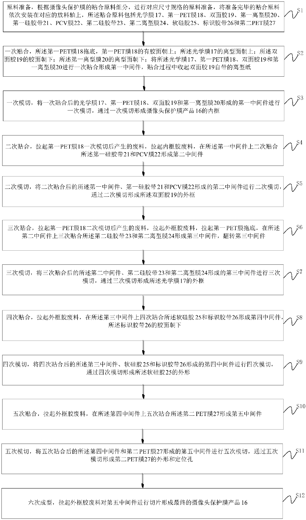
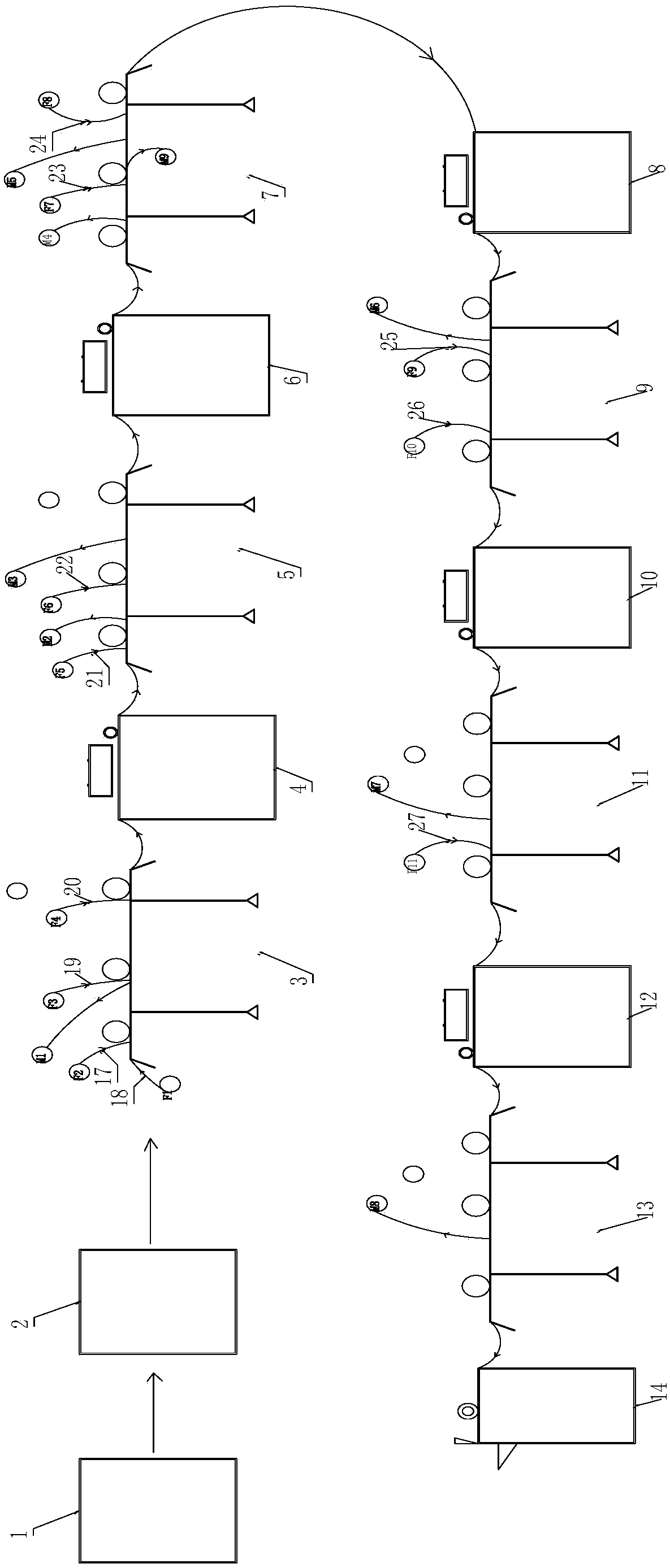
[0037] In order to make the above objects, features and advantages of the present invention more comprehensible, specific implementations of the present invention will be described in detail below in conjunction with the accompanying drawings. In the following description, numerous specific details are set forth in order to provide a thorough understanding of the present invention. However, the present invention can be implemented in many other ways different from those described here, and those skilled in the art can make similar improvements without departing from the connotation of the present invention, so the present invention is not limited by the specific embodiments disclosed below.

[0038] Unless otherwise defined, all technical and scientific terms used herein have the same meaning as commonly understood by one of ordinary skill in the technical field of the invention. The terminology used herein in the description of the present invention is only for the purpose of...


PUM


Abstract

The invention discloses a camera protection membrane, a die cutting production process and a device. The die cutting production process comprises the following steps: preparing raw materials accordingto pasting raw material components of the camera protection membrane, and sequentially mounting the prepared pasting raw materials on corresponding placing shafts, wherein a first PET (Polyethylene Terephthalate) membrane is used at the bottom, the side with an adhesive, of the first PET membrane faces upwards, the release surface of an optical membrane faces upwards, the adhesive side of a double-side adhesive faces downwards, and the release surface of a first release membrane faces downwards; carrying out primary pasting to form a first middle part, and withdrawing release paper of a double-side adhesive tape in the pasting process; carrying out primary die cutting after primary pasting, and forming an inner frame of a camera protection membrane product through primary die cutting; carrying out secondary pasting, secondary die cutting, third pasting, third die cutting, fourth pasting, fourth die cutting, fifth pasting, fifth die cutting and sixth molding in sequence, pulling up anouter frame rubber waste material, and slicing a fifth middle part, thereby finally forming a membrane carrier with a plurality of membrane products arranged in sequence. A manual combination procedure is avoided, assembling steps are reduced, the labor can be saved, and the pass percent can be increased.

Description

technical field [0001] The invention relates to a camera protective film, a die-cutting production process and a device, and relates to the technical field of film processing. Background technique [0002] With the promotion and application of electronic products, consumers have higher and higher requirements for the performance of electronic products, and have higher and higher requirements for appearance design, hardware design and software functions. At the same time, they have higher pursuit of cost performance of electronic products. . In particular, the mobile phone and notebook industries have been taking ultra-light and thin as the main development direction in recent years, and the structure and functions of electronic components are also developing in the direction of miniaturization and multi-function. The requirements for mobile phone cameras are also getting higher and higher. Before assembly, a protective film needs to be attached to avoid scratching the lens....

Claims


Application Information

Patent Timeline
Patent Type & Authority Applications(China)
IPC IPC(8): B32B33/00B32B27/06B32B27/36B32B7/12B32B9/00B32B9/04B32B27/30B32B37/02B32B38/00B32B38/10
CPCB32B7/12B32B9/00B32B9/04B32B9/045B32B27/06B32B27/30B32B27/36B32B33/00B32B37/02B32B38/0004B32B38/10
Inventor 熊有力刘东成
Owner 山东昶正智能科技有限公司
Why Eureka
Try Eureka