Check patentability & draft patents in minutes with Patsnap Eureka AI!

Image forming method of planographic printing component

A technology of lithography and imaging methods, applied in printing, printing process, printing plates, etc., can solve the problem of imaging ablation weakening the top layer, etc., and achieve the effects of reducing electrostatic source defects, reducing capacitance, and reducing voltage

Inactive Publication Date: 2002-12-25
压缩技术公司
View PDF7 Cites 0 Cited by
  • Summary
  • Abstract
  • Description
  • Claims
  • Application Information

AI Technical Summary

Problems solved by technology

Imaged ablation also weakens the topmost layer

Method used


Image

  • Image forming method of planographic printing component
  • Image forming method of planographic printing component

Examples


Embodiment Construction

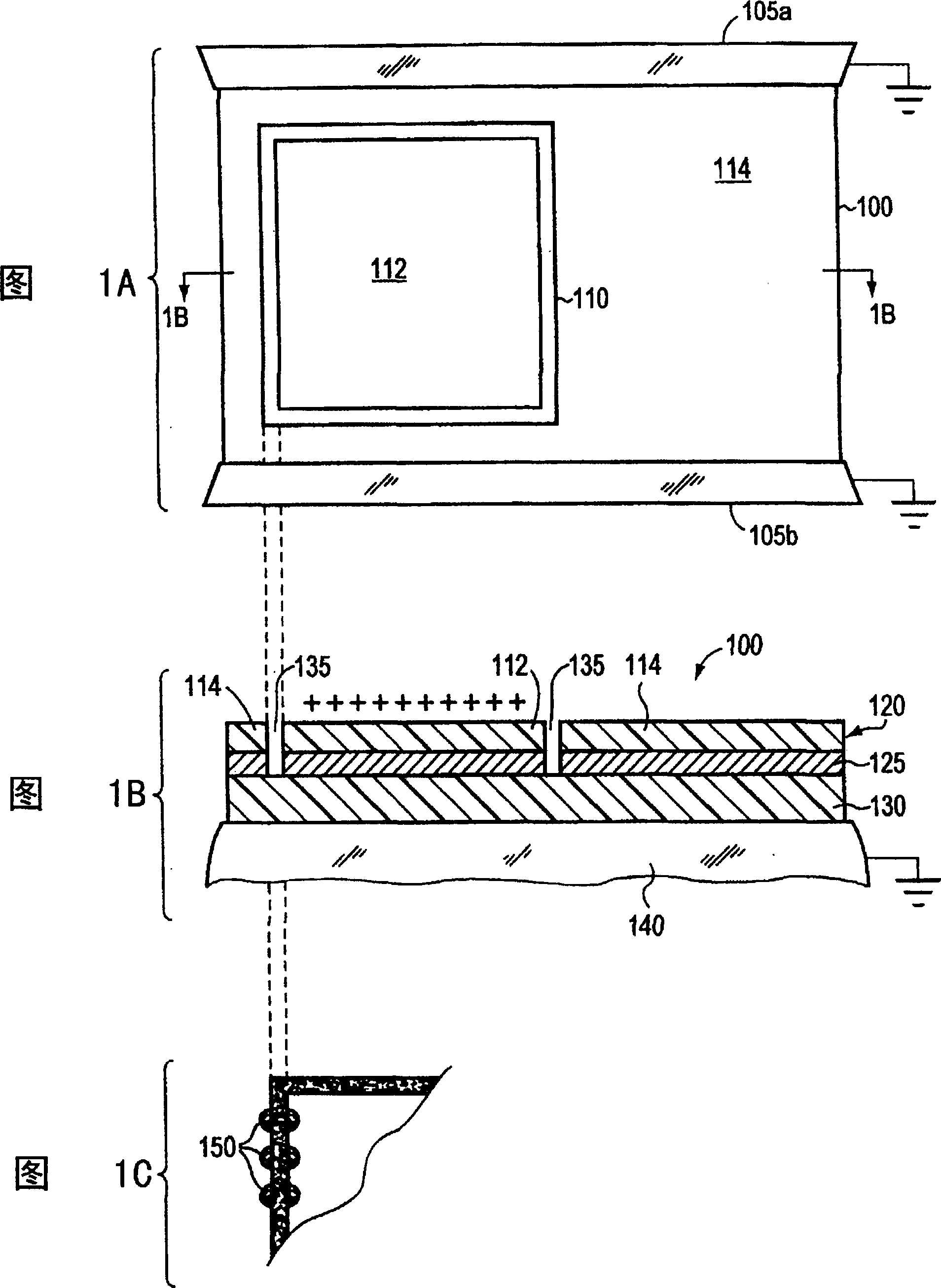
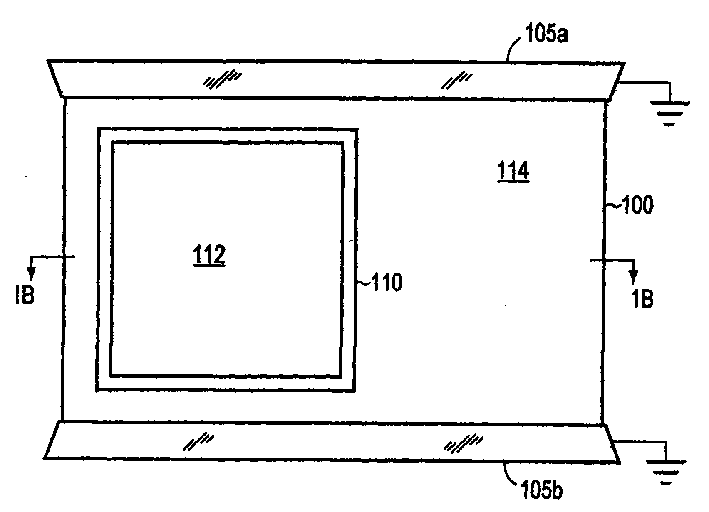
[0016] Figure 1 shows a pair of end splints 105 a 、105 b A printing plate 100 secured to a plate cylinder of a printing press or lithographic unit. The end clamps 105 are grounded through a mechanical connection to the machine frame. The printing plate 100 is ablated and imaged using an imaging apparatus such as that disclosed in the aforementioned US 5,339,737, Re 35,512, and US 5,822,345 (the entire disclosures of these patents are incorporated herein by reference). Applicable imaging devices include at least one laser device in the region of maximum plate response, i.e. at its lambda max Approximately close to the wavelength region where the printing plate absorbs the strongest emission.

[0017] Suitable imaging structures are also specified in US 5,339,737 and Re 35,512 and US 5,822,345. Briefly, the laser output can be provided directly to the surface of the printing plate via a lens or other beam directing component, or transmitted from a remote laser to the surface...


PUM


Abstract

The present invention relates to a method of imaging a lithographic printing member, avoiding electrostatic source defects in lithographic printing by reducing the insulating properties of each printing plate layer; comprising: providing a printing member comprising a polymer top layer, an imaging layer and a polymer substrate, imaging The layers are formed of a material that undergoes ablative absorption of imaging radiation, the first layer and the substrate have different affinities for the ink or for liquid that does not stick to the ink, the substrate, imaging layer, and top layer are electrically conductive; mount the plate to ground On a metal support, an electrical connection between the support and the substrate is established; at least one laser source scans the entire printed member and selectively exposes the printed member to the laser output during scanning in a pattern representative of the image to ablate the imaging layer , thereby removing the top layer and directly producing the structure of the image feature on the printed part; the structure of the image feature includes at least one boundary area isolating the unimaged area, and the electrostatic charge is applied to the top layer, and the static charge flows through the layers of the printed part to the ground .

Description

technical field [0001] The present invention relates to a digital printing device and method, in particular to a digitally controlled laser output for on-or off-press imaging of lithographic printing plates. Background technique [0002] In offset printing, the image transferred to the recording medium constitutes the ink-accepting (oleophilic) and ink-repelling (oleophobic) surface areas on the printing plate, pad, or other printing element. In a dry printing system, the printing element simply inks and transfers the image to the recording material; the printing element first contacts a driven intermediate surface called a blanket roller, which applies the image to paper or other recording medium . In a typical sheet-fed printing system, the recording medium is stapled to an impression roller, which brings the recording medium into contact with a blanket roll. [0003] In a wet lithography system, the non-image area is hydrophilic for the affinity of the fountain (or damp...

Claims


Application Information

Patent Timeline
Patent Type & Authority Patents(China)
IPC IPC(8): B41N1/14B41N1/08B41C1/10B41C1/055
CPCB41C1/1033B41C1/10
Inventor T·E·刘易斯
Owner 压缩技术公司
Features
  • R&D
  • Intellectual Property
  • Life Sciences
  • Materials
  • Tech Scout
  • Unparalleled Data Quality
  • Higher Quality Content
  • 60% Fewer Hallucinations
Learn More