Composite current collector with electrical interconnection and through-hole structure, preparation method thereof, battery pole pieces and lithium ion battery

A current collector and electrical interconnection technology, applied in battery electrodes, electrode current collector coatings, electrode carriers/current collectors, etc., can solve the incompatibility of laminated welding processes, the inability of welding strength and overcurrent area to be guaranteed, and the deterioration of batteries. performance and other issues, to achieve the effect of improving current distribution and power output capability, ensuring welding strength and overcurrent area, and improving capacity.

Inactive Publication Date: 2019-04-30
CHINA AVIATION LITHIUM BATTERY RES INST CO LTD +1
View PDF8 Cites 18 Cited by
  • Summary
  • Abstract
  • Description
  • Claims
  • Application Information

AI Technical Summary

Problems solved by technology

Due to the double-sided coating of lithium-ion battery pole pieces, the current collector structure will lead to uneven electric field distribution on both sides of the battery during battery use and deteri

Method used


Image

  • Composite current collector with electrical interconnection and through-hole structure, preparation method thereof, battery pole pieces and lithium ion battery
  • Composite current collector with electrical interconnection and through-hole structure, preparation method thereof, battery pole pieces and lithium ion battery

Examples


Embodiment 1

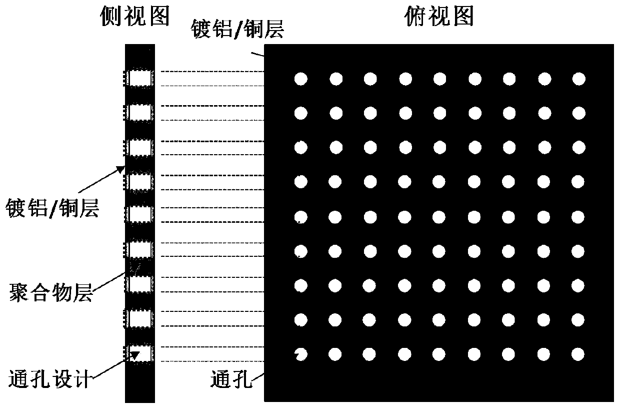
[0035]Put the 5μm PET film layer in the vacuum metallization device, under the vacuum state, the aluminum metal is heated and melted until it evaporates, and the aluminum atoms condense on the surface of the PET film layer to form an extremely thin aluminum layer. By precisely controlling the PET film take-up speed to 500m / min, while controlling the aluminum feeding speed to 0.3m / min@2mm aluminum wire and the heating current of the evaporation boat, a metal coating with a thickness of 0.1μm is obtained on the surface of the PET film. Using CO 2 A laser generator creates holes. Specifically, 10.6μm CO with 500W high pulse intensity was selected. 2 The laser uses the high intensity of the laser pulse to cause the local heating and melting of the PET film layer to obtain a through hole with a diameter of 1mm. At the same time, the scanning mirror system is used to flexibly select the distance between the holes to 2mm. The obtained through-hole PET film layer is placed in a vac...

Embodiment 2

[0040] The 8μm PET film layer is placed in a vacuum metallization device. In a vacuum state, the aluminum metal is heated and melted until it evaporates, and the aluminum atoms condense on the surface of the PET film layer to form an extremely thin aluminum layer. By precisely controlling the PET film take-up speed to 400m / min, while controlling the aluminum feeding speed to 0.2m / min@2mm aluminum wire and the heating current of the evaporation boat, a metal coating with a thickness of 0.1μm is obtained on the surface of the PET film. Using CO 2 A laser generator creates holes. Specifically, 10.6μm CO with 300W high pulse intensity was selected. 2 The laser uses the high intensity of the laser pulse to cause the local heating and melting of the PET film layer to obtain a through hole with a diameter of 0.3mm. At the same time, the scanning mirror system is used to flexibly select the distance between holes to 3mm. The obtained through-hole PET film layer is placed in a vacuu...

Embodiment 3

[0045] The 10μm PET film layer is placed in a vacuum metallization device. In a vacuum state, the aluminum metal is heated and melted until it evaporates, and the aluminum atoms condense on the surface of the PET film layer to form an extremely thin aluminum layer. By precisely controlling the PET film take-up speed to 300m / min, while controlling the aluminum feeding speed to 0.3m / min@2mm aluminum wire and the heating current of the evaporation boat, a metal coating with a thickness of 0.2μm is obtained on the surface of the PET film. Using CO 2 A laser generator creates holes. Specifically, 10.6μmCO with 500W high pulse intensity was selected 2 The laser uses the high intensity of the laser pulse to cause the local heating and melting of the PET film layer to obtain a through hole with a diameter of 0.5mm. At the same time, the scanning mirror system is used to flexibly select the distance between the holes to 4mm. The obtained through-hole PET film layer is placed in a va...


PUM

PropertyMeasurementUnit
Thicknessaaaaaaaaaa
Thicknessaaaaaaaaaa
Thicknessaaaaaaaaaa

Abstract

The invention relates to a composite current collector with electrical interconnection and a through-hole structure, a preparation method thereof, battery pole pieces and a lithium ion battery, and belongs to the technical field of lithium ion batteries. The preparation method of the composite current collector includes the following steps: (1) coloring, casting and forming to prepare a polymer base layer; (2) carrying out first vacuum metal plating on the surface of the polymer base layer; (3) making holes in the surface of the metal-coated polymer layer; and (4) carrying out second vacuum metal plating on the surface of the polymer layer. The prepared current collector is of an inner and outer double-layer structure with the through-hole structure. The inner layer is a polymer layer withthe through-hole structure, and the surface layers are metal coatings. The metal coatings cover the surface of the through holes, the through holes communicate the metal coatings. The preparation method is simple and easy in large-scale production, and can customize the thickness and hole structure distribution according to specific application indicator. Compared with a conventional foil material, the composite current collector with the electrical interconnection and the through-hole structure has the advantages of light weight, bending resistance, low cost and the like, and has a significant effect on the energy density improvement of the battery.

Description

technical field [0001] The invention belongs to the technical field of lithium ion batteries. In particular, it relates to a composite current collector with electrical interconnection and through-hole structure, a preparation method thereof, and an application in lithium-ion batteries. Background technique [0002] Due to the advantages of high efficiency, cleanliness, and recyclability, lithium-ion batteries are considered to be an important energy storage device to comprehensively alleviate energy crisis and environmental pollution. In recent years, with the rapid development of the electric vehicle industry, lithium-ion batteries, one of its core components, have received extensive attention and in-depth research from all walks of life. However, the current mileage and cost of electric vehicles cannot effectively compete with traditional fuel vehicles, which has greatly hindered the rapid promotion of electric vehicles. The improvement of energy density and cost reduct...

Claims


Application Information

Patent Timeline
IPC IPC(8): H01M4/80H01M4/66H01M4/04H01M10/0525H01M10/058
CPCH01M4/0404H01M4/0433H01M4/0471H01M4/0483H01M4/667H01M4/80H01M10/0525H01M10/058H01M2220/20Y02E60/10Y02P70/50
Inventor 肖亚洲潘芳芳单旭意王志敏乔智
Owner CHINA AVIATION LITHIUM BATTERY RES INST CO LTD
Why Eureka
Try Eureka