
Millimeter wave differential coplanar feeding dielectric antenna

A dielectric antenna and differential feeding technology, which is applied in the field of communication, can solve the problems of large assembly error, large assembly error, different layers of antenna and feed network, etc., and achieve the effect of reducing assembly error and volume

Active Publication Date: 2019-05-03
NANTONG UNIVERSITY
View PDF4 Cites 1 Cited by
  • Summary
  • Abstract
  • Description
  • Claims
  • Application Information

AI Technical Summary

Problems solved by technology

When this type of antenna is finally realized, the patch dielectric resonator needs to be adhered to the substrate, so there will be a large assembly error
In addition, the common problem of the above two types of antennas is that the antenna and feed network need to be designed in different layers, and then the final assembly
This approach is still a high-profile structure to a certain extent, and it is not convenient for integrated processing, and the assembly error is also large

Method used


Image

  • Millimeter wave differential coplanar feeding dielectric antenna
  • Millimeter wave differential coplanar feeding dielectric antenna
  • Millimeter wave differential coplanar feeding dielectric antenna

Examples


Embodiment Construction

[0022] In order to facilitate the understanding of the present invention, the present invention will be described more fully below with reference to the associated drawings. Typical embodiments of the invention are shown in the drawings. However, the present invention can be embodied in many different forms and is not limited to the embodiments described herein. Rather, these embodiments are provided so that the disclosure of the present invention will be thorough and complete.

[0023] It should be noted that the terms "vertical", "horizontal", "left", "right" and similar expressions used herein are for illustrative purposes only. Unless otherwise defined, all technical and scientific terms used herein have the same meaning as commonly understood by one of ordinary skill in the technical field of the invention. The terms used herein in the description of the present invention are for the purpose of describing specific embodiments only, and are not intended to limit the pres...


PUM


Abstract

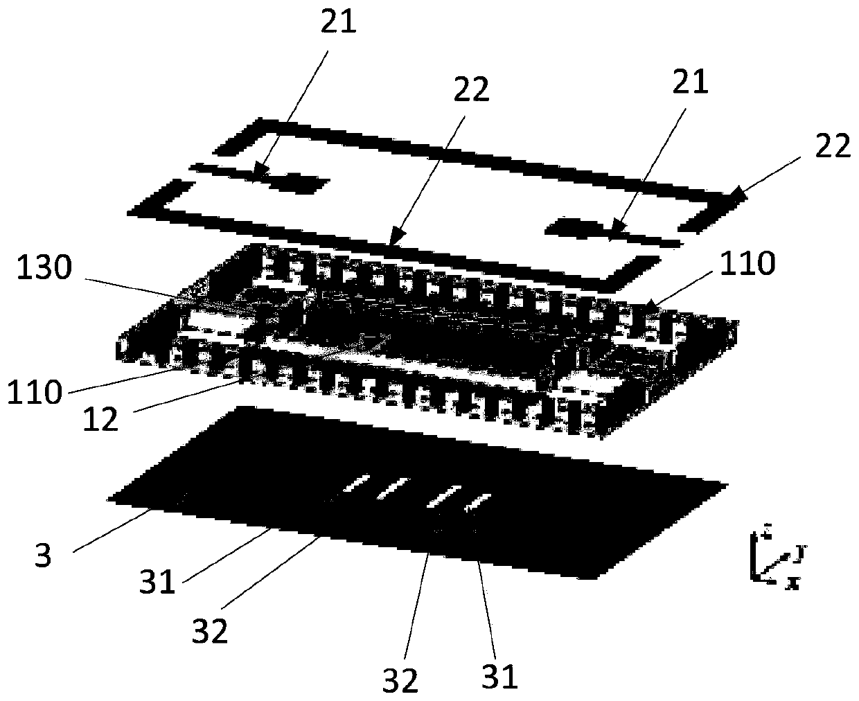
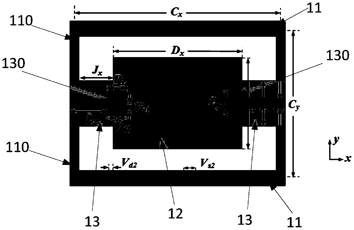
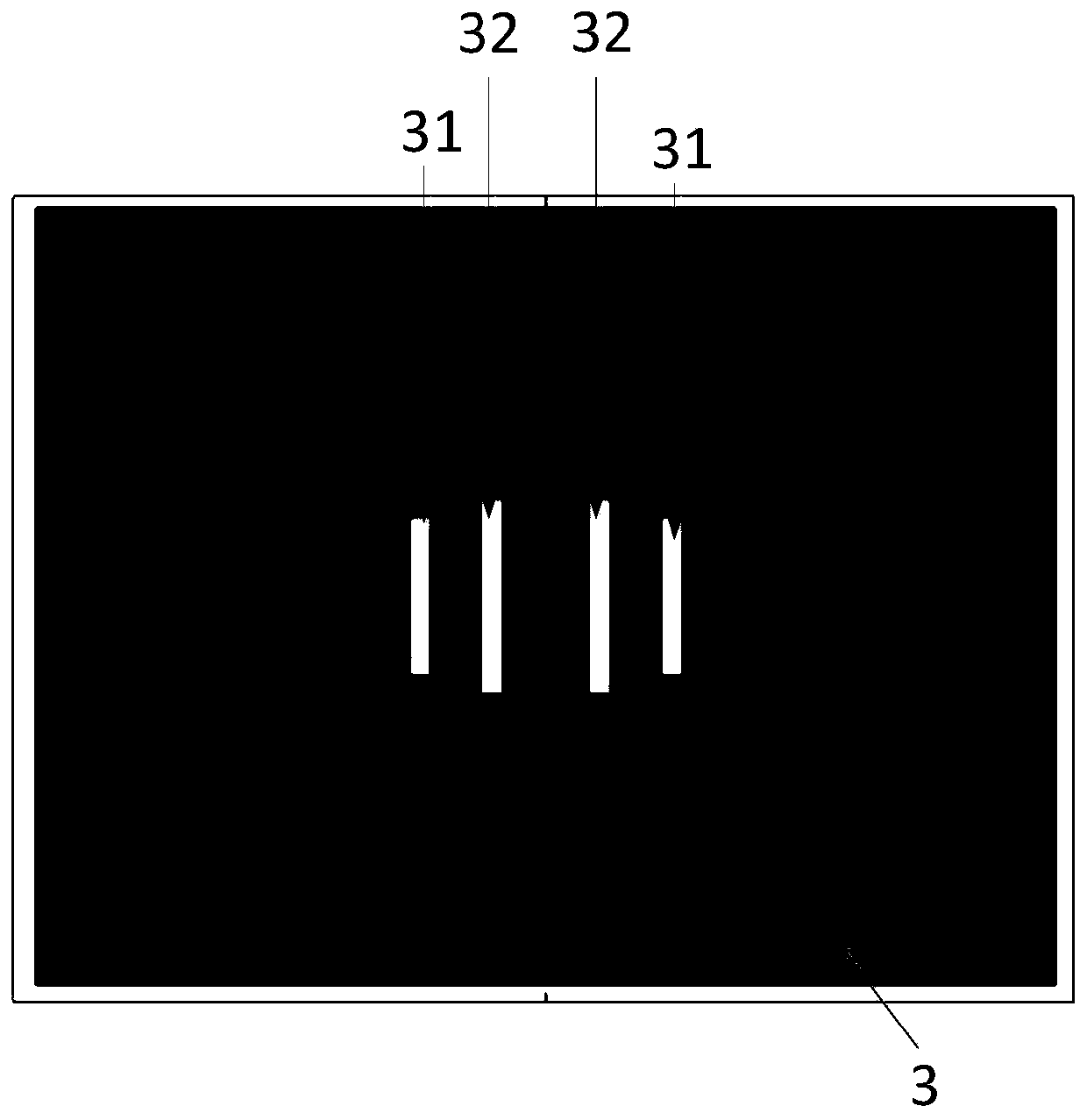
The invention discloses a millimeter wave differential coplanar feeding dielectric antenna, which comprises a rectangular dielectric substrate, a pair of differential feeding structures arranged on the upper surface of the dielectric substrate, and a metal ground arranged on the lower surface of the rectangular dielectric substrate, wherein the partial region of the substrate is etched and removedto form a rectangular ring-shaped substrate contour portion, a rectangular dielectric resonator surrounded by the substrate contour portion, and a pair of connecting arms; a first metallized via holeis formed in each of the pair of connecting arms; one end of each differential feeding structure is used for accessing a differential signal, and the other end is connected to the metal ground by means of the corresponding first metallized via hole. The millimeter wave differential coplanar feeding dielectric antenna feeds coplanarly to realize the low profile design of the antennas of this type,meanwhile, the antenna can be implemented by adopting a single-layer printed circuit board process, and the assembly errors of the antenna are further reduced; secondly, by adopting the differentialexcitation, the antenna has low cross polarization and can be directly integrated with the differential circuit, and the antenna has a filtering function by means of two pairs of slits having different lengths.

Description

technical field [0001] The invention relates to the field of communication, in particular to a dielectric antenna for millimeter wave differential coplanar feeding. Background technique [0002] As the operating frequency of the wireless communication system is gradually increased to the millimeter wave frequency band, high speed, high signal-to-noise ratio and low delay have become the main requirements for system design. In the face of such problems, a circuit with a differential topology will effectively improve the signal quality. At the same time, due to the short operating wavelength of the millimeter wave band and the existence of the skin effect, the antenna made of metal often has a large ohmic loss, which reduces the radiation efficiency of the antenna. At this time, the dielectric antenna has been widely concerned and researched due to its low loss and high efficiency in the millimeter wave frequency band. [0003] In order to accommodate the high device integra...

Claims


Application Information

Patent Timeline
IPC IPC(8): H01Q1/36H01Q1/48H01Q1/50H01P1/20
Inventor 唐慧仝昌武陈建新
Owner NANTONG UNIVERSITY
Learn More