
Vortex light-based rotating object rotary shaft tilt angle detection device

A detection device and a technology of vortex light, which are applied to devices using optical methods, measuring devices, and optical devices, etc., can solve problems such as inability to obtain effectively, and achieve the effects of novel technology, simple operation, and fast measurement speed

Active Publication Date: 2019-05-07
PLA PEOPLES LIBERATION ARMY OF CHINA STRATEGIC SUPPORT FORCE AEROSPACE ENG UNIV
View PDF5 Cites 17 Cited by
  • Summary
  • Abstract
  • Description
  • Claims
  • Application Information

AI Technical Summary

Problems solved by technology

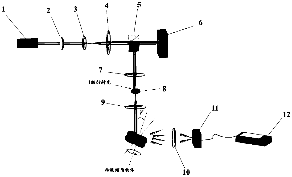
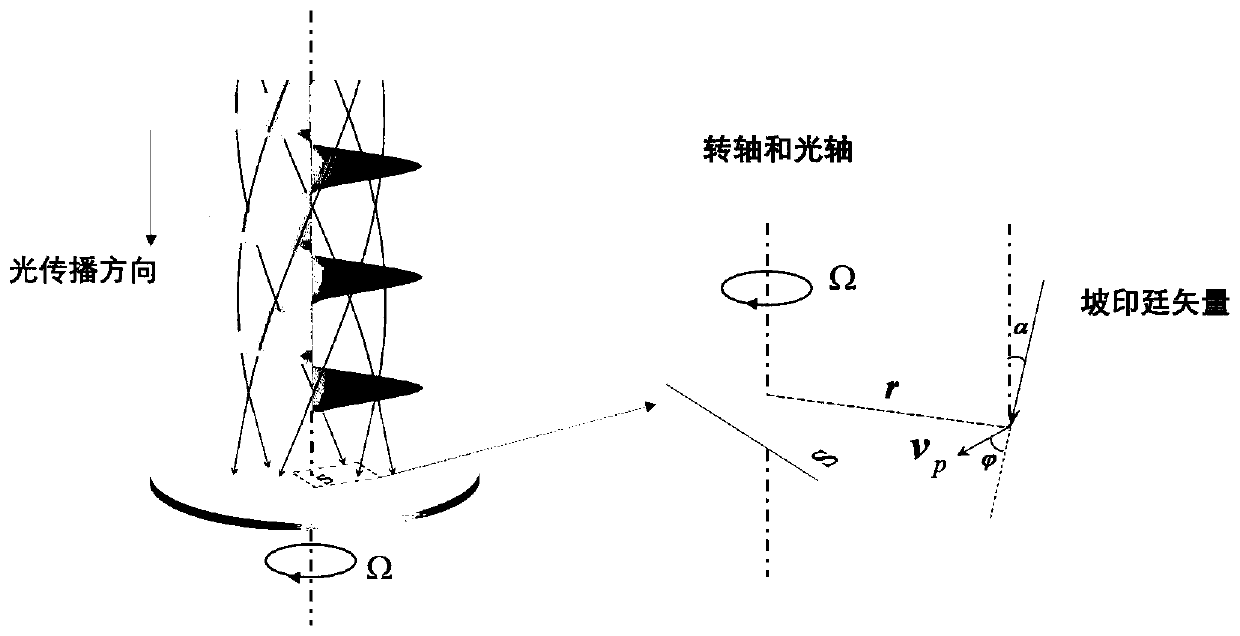
[0015] The problem solved by the technology of the present invention is: aiming at the problem that the existing non-contact detection device for rotating objects can only obtain the information of the rotation rate of the object but cannot effectively obtain the information of the direction (posture) of the object's rotation axis, a device that can effectively obtain A device for tilting an object's axis of rotation

Method used


Image

  • Vortex light-based rotating object rotary shaft tilt angle detection device
  • Vortex light-based rotating object rotary shaft tilt angle detection device
  • Vortex light-based rotating object rotary shaft tilt angle detection device

Examples


Embodiment Construction

[0055] specific implementation plan

[0056] In the present invention, the superposition vortex beam is used as the detection carrier, and the specific implementation steps are as follows:

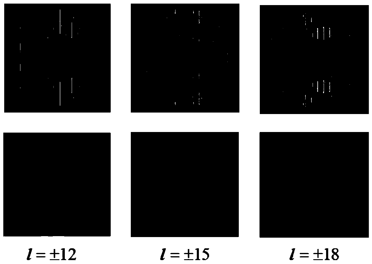
[0057] Firstly, the laser (1) generates a laser beam, which becomes horizontally polarized light after passing through the polarizer (2), and the Gaussian beam of the required diameter is irradiated on the SLM through the collimator beam expander lens group 1 and 2, and the SLM is loaded Hologram, an example of a loaded hologram and the corresponding vortex spot such as figure 2 shown.

[0058] Next, the vertically polarized light beam generated by SLM modulation is reflected by the polarization beam splitter prism (5), and then passes through the 4f filter system composed of convex lens (7), pinhole diaphragm (8) and convex lens (9) in turn, and selects the The first-order diffracted light generated by the SLM is collimated. Note that the diaphragm should be placed where the focal poin...


PUM


Abstract

The invention relates to a vortex light-based rotating object rotary shaft tilt angle detection device. The device mainly comprises a He-Ne laser, a polarizing plate, a lens group, a polarization beamsplitting prism, a space light modulator, a 4f filter system, a plano-convex lens, a photoelectric detector, and a mini oscillometer. First, the laser generates Gaussian beam, after being collimated,the beam irradiates the space light modulator loaded with a specific hologram so as to prepare vortex light in overlaid state; then, the vortex light irradiates the center of the rotary shaft of a rotating object, after the vortex light is scattered by the object, scattered light is collected by the convex lens; finally, the photoelectric detector detects strength change of scattered beam and transmits a signal to the oscillometer, the oscillometer performs Fourier transformation, and a tile angle of the rotary shaft of the object relative to a beam incident direction can be determined according to spectrum bandwidth information. The device has a simple structure, can work effectively even in extreme conditions.

Description

technical field [0001] The invention mainly relates to the fields of optics, physics, photoelectric conversion, and signal detection, especially technical methods such as phase modulation and beat frequency detection of light beams. technical background [0002] The technical background of the invention is mainly based on the rotational Doppler effect. The classic Doppler effect (LDE) is caused by the linear relative velocity between the object and the wave source. Due to the relative rotation speed between them, it has not been practically applied. The generation of the rotating Doppler effect requires a probe wave source with a rotational velocity around the propagation axis. In the field of classical physics, this wave source can transmit a Laguerre-Gaussian beam through a rotating Dove prism (Dove) or a 1 / 4 wave plate. get. [0003] Since Allen discovered photon orbital angular momentum (OAM) in 1992, the characteristics of vortex light carrying OAM have been graduall...

Claims


Application Information

Patent Timeline
IPC IPC(8): G01B11/26G01P3/36
Inventor 任元邱松刘通李智猛王琛邵琼玲陈晓岑
Owner PLA PEOPLES LIBERATION ARMY OF CHINA STRATEGIC SUPPORT FORCE AEROSPACE ENG UNIV
Learn More