Method for manufacturing N-type selective emitter double-sided battery by spin-coating boron source laser doping

A technology of laser doping and double-sided batteries, applied in photovoltaic power generation, circuits, electrical components, etc., to achieve the effects of reducing contact resistance, improving electrical performance, and reducing the rate of minority carrier recombination

Inactive Publication Date: 2019-05-10
EAST CHINA UNIV OF SCI & TECH +1
View PDF11 Cites 18 Cited by
  • Summary
  • Abstract
  • Description
  • Claims
  • Application Information

AI Technical Summary

Problems solved by technology

[0005] The purpose of the present invention is to provide a method for manufacturing N-type selective emitter double-sided cells by laser doping of spin-coated boron source in order to overcome the defects of the above-mentioned prior art, which solves some problems existing in the prior art in industrialization

Method used


Image

  • Method for manufacturing N-type selective emitter double-sided battery by spin-coating boron source laser doping
  • Method for manufacturing N-type selective emitter double-sided battery by spin-coating boron source laser doping
  • Method for manufacturing N-type selective emitter double-sided battery by spin-coating boron source laser doping

Examples


preparation example Construction

[0019] A method for fabricating N-type selective emitter double-sided batteries by spin-coating boron source laser doping solves some problems existing in the prior art in industrialization. In the production of N-type double-sided cells, one of the main factors restricting cell efficiency is the high contact resistance between the electrode metallization and the silicon body and the increase in the minority carrier recombination rate caused by the high boron doping concentration on the surface. The invention adopts spin-coated boron source to coat the front surface, diffuses in a diffusion furnace to form a lightly doped emitter, and adopts BSG laser doping formed after diffusion to form a heavily doped emitter. The preparation method of the boron source used in this method is simple, and the cost is lower than other boron diffusion methods. The selective emitter is doped with BSG laser formed after the boron source is diffused. Compared with other selective emitters, the oper...
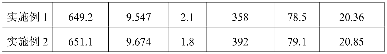
Embodiment 1

[0030] Use an N-type silicon wafer with a resistivity of 1 to 8, dry it after making texture, first spin coat 1ml of pre-wetting liquid on the surface of the silicon wafer, and then spin coat 0.5ml of boron source, and set the spin coating speed at 2500r / min. The rotation time is 5s, and finally the organic phase in the boron source is dried at 200°C. The silicon wafer with spin-coated boron source is placed in a tubular diffusion furnace to diffuse to form a front emitter, and the front surface resistance is controlled between 60-70.

[0031] After the above operations are completed, use 5% to 10% HF acid to clean and remove the oxide on the back of the silicon wafer, and the phosphorus-doped back field on the back uses PClO 3 Formed by high-temperature diffusion method, the diffusion resistance is controlled at 60-100ohm / sq.

[0032] Further, use 5% to 10% HF acid to clean and remove the oxides on the front and back, and use SiN X / SiO 2 The passivation anti-reflection fi...

Embodiment 2

[0035] Use an N-type silicon wafer with a resistivity of 1 to 8, dry it after making texture, first spin coat 1ml of pre-wetting liquid on the surface of the silicon wafer, and then spin coat 0.5ml of boron source, and set the spin coating speed at 2500r / min. The rotation time is 5s, and finally the organic phase in the boron source is dried at 200°C. Put the spin-coated boron source silicon wafer into the tubular diffusion furnace to diffuse to form a lightly doped emitter. After diffusion, a thick BSG is formed on the surface of the silicon wafer, and laser doping is used to form a heavily doped emitter.

[0036] In the above embodiments, the square resistance of the lightly doped emitter region is 80˜200 ohm / sq, and the square resistance of the heavily doped emitter region is 10˜70 ohm / sq.

[0037] After the above operations are completed, use 5% to 10% HF acid to clean and remove the oxide on the back of the silicon wafer, and the phosphorus-doped back field on the back us...


PUM

PropertyMeasurementUnit
thicknessaaaaaaaaaa
wavelengthaaaaaaaaaa
thicknessaaaaaaaaaa

Abstract

The invention relates to a method for manufacturing an N-type selective emitter double-sided battery by spin-coating boron source laser doping. The method comprises the following steps: texturing an N-type silicon wafer; adopting a spin-coating method for spin-coating the front surface of an organic boron source and then drying the organic boron source; carrying out diffusion in a diffusion furnace to form a front lightly doped emitter; carrying out front BSG laser doping to form a heavily doped emitter; cleaning the back surface to remove PSG; carrying out back phosphorus diffusion to form aphosphorus back field; carrying out front and back deposition on an anti-reflective passivation film; and printing front and back electrodes to complete the battery production. Compared with the priorart, the boron source is coated on the front surface of the silicon wafer by adopting the spin coating method, and selective laser doping is carried out by using the BSG formed on the front side after diffusion, so that a region below an electrode is heavily doped with boron, thus the contact resistance is effectively reduced; and a non-electrode region adopts lightly doped boron to reduce the composite of the front surface, so that the electrical performance of the battery is effectively improved.

Description

technical field [0001] The invention relates to the field of N-type double-sided solar cells, in particular to a method for manufacturing N-type selective emitter double-sided cells by spin-coating boron source laser doping. Background technique [0002] The research and development and industrial practice of solar photovoltaic technology in the past 30 years have established the mainstream position of silicon photovoltaic technology based on crystalline silicon substrates. According to the conductivity type of the crystalline silicon substrate, silicon wafers can be divided into two types: P-type and N-type. Due to its natural advantages such as high minority carrier lifetime and no light-induced attenuation, N-type crystalline silicon cells have greater room for efficiency improvement and stability, and have become a focus of industry attention and research. [0003] When the doping concentration of the front emission region is too high, the recombination rate of minority...

Claims


Application Information

Patent Timeline
Patent Type & Authority Applications(China)
IPC IPC(8): H01L31/068H01L31/18
CPCY02E10/547Y02P70/50
Inventor 杨金霖袁晓李红波柳翠梁海杨宁李士正
Owner EAST CHINA UNIV OF SCI & TECH
Why Eureka
Try Eureka