
Stop-band coding-controllable surface plasmon transmission line and control method thereof

A surface plasmon and coding control technology, applied in the field of radio frequency transmission lines, can solve the problems of narrow stop band and poor transmission stability, and achieve the effects of fast control speed, avoiding processing errors and convenient operation

Inactive Publication Date: 2019-05-10
SOUTHEAST UNIV
View PDF1 Cites 7 Cited by
  • Summary
  • Abstract
  • Description
  • Claims
  • Application Information

AI Technical Summary

Problems solved by technology

For example, by placing the ring resonator close to the surface plasmon waveguide, the resonance of the ring resonator will introduce a narrow stopband whose center frequency can be tuned by controlling the resonance response of the ring resonator, but the strong resonance of the ring resonator will Bringing disadvantages such as poor transmission stability and narrow stop band

Method used


Image

  • Stop-band coding-controllable surface plasmon transmission line and control method thereof
  • Stop-band coding-controllable surface plasmon transmission line and control method thereof
  • Stop-band coding-controllable surface plasmon transmission line and control method thereof

Examples


Embodiment Construction

[0021] The technical solutions of the present invention will be described in detail below in conjunction with the accompanying drawings and specific embodiments.

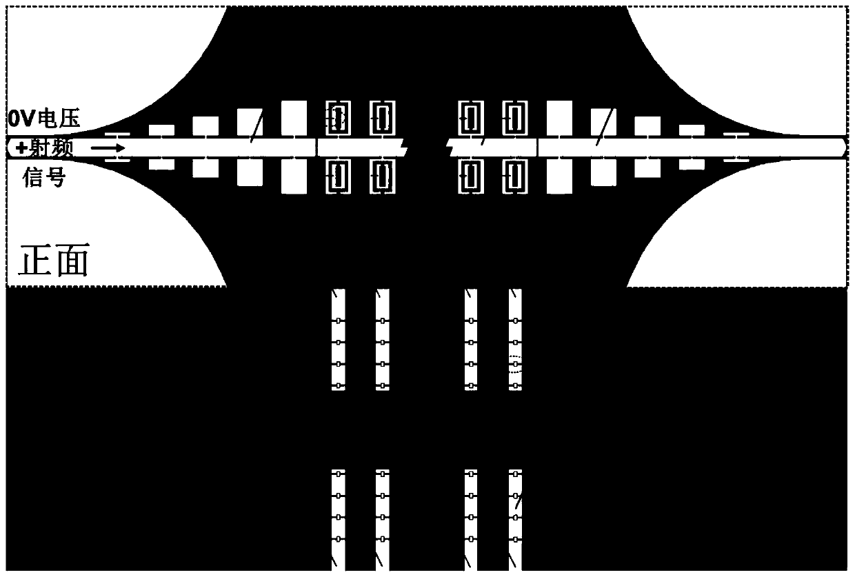
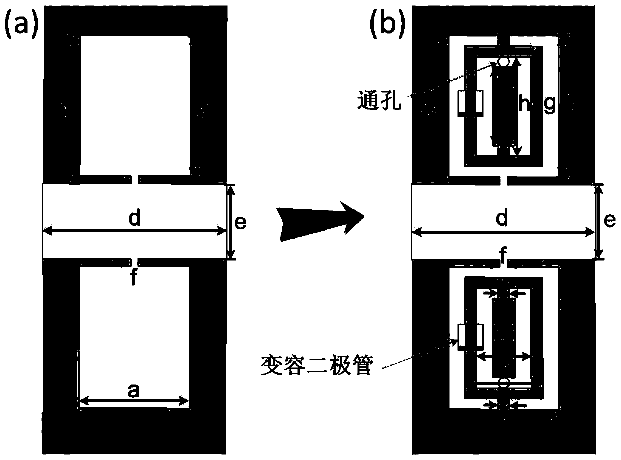
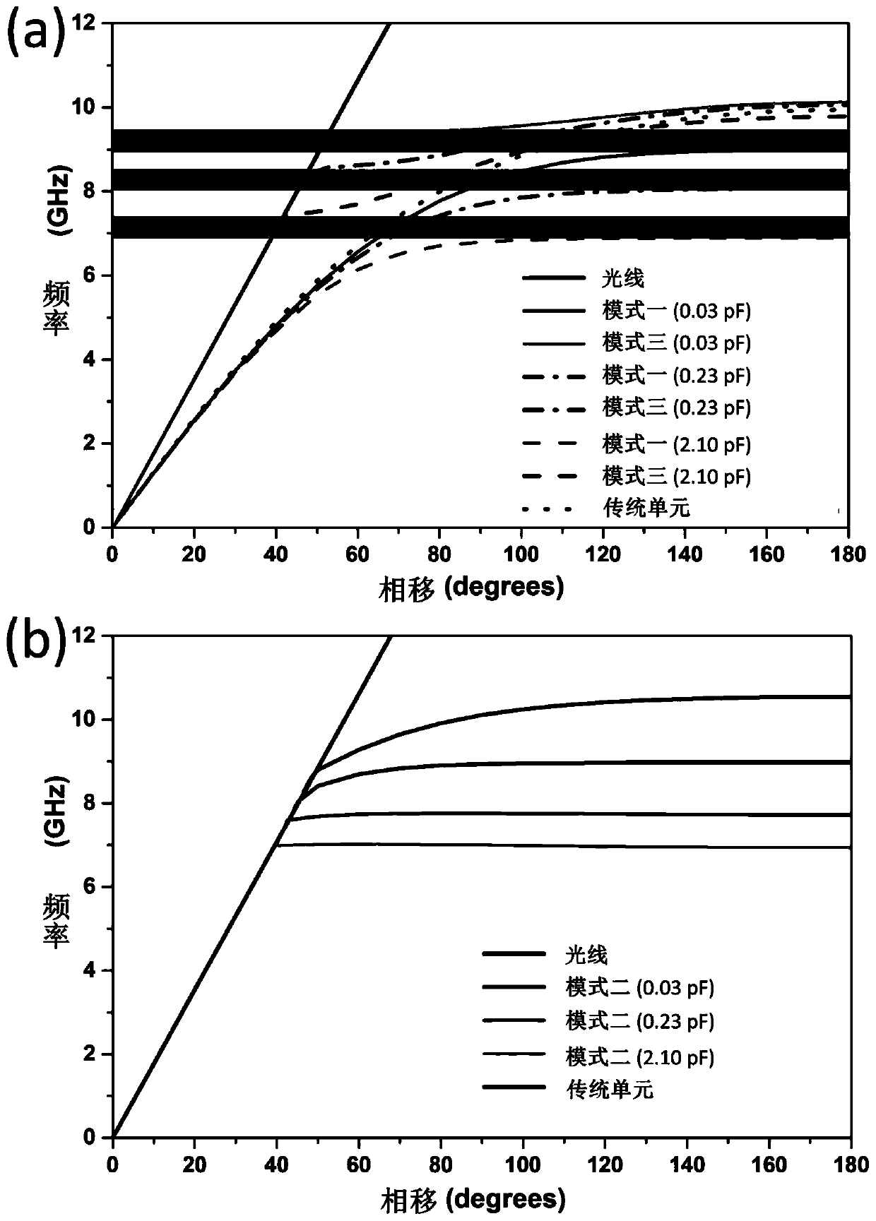
[0022] figure 1 is the overall model of the stop-band coded controllable surface plasmon transmission line proposed, including the dielectric substrate, the artificial surface plasmon structure on the front of the dielectric substrate, and several radio frequency high-resistance lines on the back of the dielectric substrate, among which the artificial surface, etc. The plasmon structure includes a first metal strip 2, two transition sections 1 and 3, and several coded artificial surface plasmon units, the two transition sections are respectively located at both ends of the transmission line and connected to the tapered coplanar waveguide structure, and The transition section is connected to the first metal strip and arranged symmetrically on both sides of the first metal strip; the coded artificial surface plasmon u...


PUM


Abstract

The invention discloses a stop-band coding-controllable surface plasmon transmission line and a control method thereof. The transmission line comprises a medium substrate, an artificial surface plasmon structure located on the front of the medium substrate, and a plurality of radio frequency high-resistance lines located on the back of the medium substrate; the artificial surface plasmon structurecomprises a first metal strip, two transition sections and a plurality of coding artificial surface plasmon units; two transition sections are located at two ends of the transmission line and connected with gradually changed coplanar waveguide structures; the transition sections are connected with the first metal strip and symmetrically arranged at two sides of the first metal strip; the coding artificial surface plasmon units are located between the transition sections and corresponding to the radio frequency high-resistance lines on the back of the medium substrate one by one; each coding artificial surface plasmon unit is provided with a variable capacitance diode, and connected with the first metal strip and the radio frequency high-resistance line on the back of the medium substrate.A multichannel radio frequency signal synchronous modulation function is realized, and the multi-path channel information transmission function is finally realized.

Description

technical field [0001] The invention relates to a radio frequency transmission line, in particular to a stopband coding controllable surface plasmon transmission line. Background technique [0002] Surface plasmon is a surface electromagnetic wave mode, which is distributed at the interface between metal and medium, and tightly binds electromagnetic energy in a small area around the interface. It has sub-wavelength characteristics in the optical band and can be effectively transmitted. and localized light waves, which are widely used in optical communication systems. However, metals exhibit ideal electrical conductor properties in the microwave range, and cannot directly support surface plasmons at the interface between metal and dielectric. Therefore, an artificial surface plasmon based on a planar metal slot structure was proposed, whose dispersion characteristics are consistent with surface plasmon, which provides the possibility for designing planar plasmon devices. ...

Claims


Application Information

Patent Timeline
Patent Type & Authority Applications(China)
IPC IPC(8): H01P3/00
Inventor 马慧锋王萌孙实汪会川田素成崔铁军
Owner SOUTHEAST UNIV
Learn More