

Mobile terminal millimeter wave phased array magnetic dipole antenna and mobile terminal millimeter wave phased array magnetic dipole antenna array
A technology for magnetic dipole antennas and mobile terminals, applied to antenna arrays, antennas, and resonant antennas that are powered separately, can solve problems such as the inability to meet the needs of all-round signal coverage of handheld terminal equipment, and achieve mass production and ease of use. The effect of large angle coverage and wide beamwidth
- Summary
- Abstract
- Description
- Claims
- Application Information
AI Technical Summary
Problems solved by technology
Method used
Image

Examples
Embodiment 1
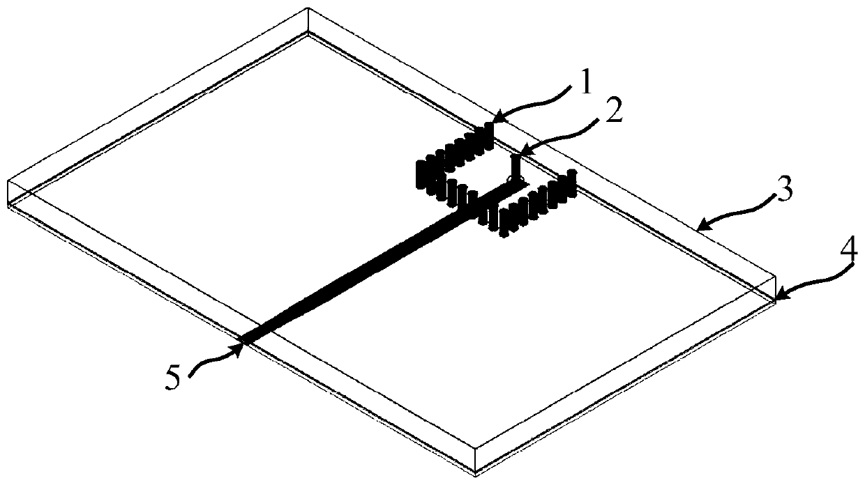
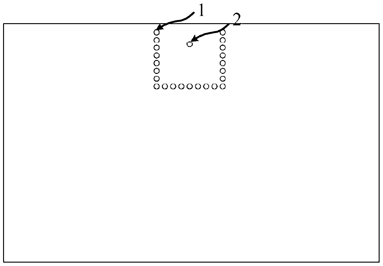
[0037] Such as figure 1 A magnetic dipole antenna based on a semi-open substrate integrated waveguide resonator in this embodiment, Figure 4 It is an antenna array composed of magnetic dipole antennas based on semi-open substrate integrated waveguide resonators.
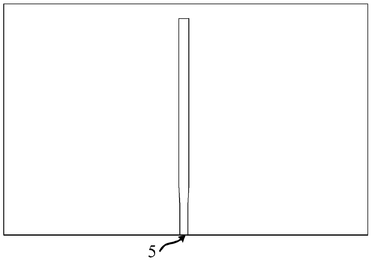
[0038] figure 1 A magnetic dipole antenna based on a semi-open substrate integrated waveguide resonator, including an upper dielectric plate and a lower dielectric plate, wherein the material of the upper dielectric plate is Taconic TLY-5, the thickness is 1.52mm, and the upper dielectric plate is The upper surface and the lower surface are respectively provided with a first metal floor 3 and a second metal floor 4, and the metallized via hole group 1 contained in the upper dielectric plate constitutes a semi-open substrate integrated waveguide resonator cavity, and the metallized via hole The hole period of group 1 is 0.75mm, the width of the formed semi-open substrate integrated waveguide resonator is 6.4mm, the...
Embodiment 2
[0045] Such as Figure 7 with Figure 8 As shown, in order to make the antenna beam scan, on the basis of Embodiment 1, another phase-shifting feed network 7 realized by a microstrip power divider with equal amplitude and different phases is adopted, and each array unit will obtain equal-amplitude and different-phase motivating signal. Figure 7 is the metallized via hole position diagram corresponding to the antenna array, using the metallized via hole group consistent with embodiment 1, the feeding probe 2 of each antenna unit in this embodiment is located in the metallized via hole group 1 to form a half The central axis of the open substrate integrated waveguide resonant cavity is located on the upper side to achieve good impedance matching performance. Figure 8 The phase-shifted feed network 7 showing microstrip lines with equal amplitude and different phases is composed of three one-to-two microstrip equal-power dividers to realize the function of one-to-four equal-po...
PUM
| Property | Measurement | Unit |
|---|---|---|
| Thickness | aaaaa | aaaaa |
| Thickness | aaaaa | aaaaa |
Abstract
Description
Claims
Application Information