Full-hydraulic deep well drilling machine

A fully hydraulic and hydraulic technology, applied in rotary drilling rigs, drill pipes, drill pipes, etc., can solve the problems of irreparable time, normal construction, and underground temperature rise, avoiding operation interference and facilitating high power. Integrated intelligent control, the effect of reducing the applied load

Active Publication Date: 2019-05-14
JILIN UNIV
View PDF14 Cites 13 Cited by
  • Summary
  • Abstract
  • Description
  • Claims
  • Application Information

AI Technical Summary

Problems solved by technology

[0008] First, the hoisting-lowering of the drill string and pipe handling operations and normal drilling operations are two non-overlapping work processes, and the auxiliary time occupied by lifting-lowering the drill string and screwing-unthreading of the drill pipe joint is the longest, Time spent lifting or lowering the empty stroke cannot be compensated by using only one main lift
[0009] Second, the drilling fluid circulation of deep well drilling is the main technical means to ensure the smooth discharge of slag cuttings and prevent buried drilling. In the traditional process of lifting and lowering the drill string, the mud circulation must be closed when screwing and unloading the drill pipe joint. It causes downhole temperature to rise, affects the subsequent drilling process, and also brings the risk of wellbore instability and drilling burial
[0010] Thirdly, the reliability of deep well drilling equipment is very critical. The routine maintenance and troubleshooting of equipment will consume necessary time. Only one set of operating devices cannot carry out normal construction during the maintenance and troubleshooting process, even if necessary technical measures can be taken. measures, there is still the risk of underground accidents

Method used


Image

  • Full-hydraulic deep well drilling machine
  • Full-hydraulic deep well drilling machine
  • Full-hydraulic deep well drilling machine

Examples


Embodiment Construction

[0046] In order to illustrate the present invention more clearly, the present invention will be further described below in conjunction with preferred embodiments and accompanying drawings. Those skilled in the art should understand that the content specifically described below is illustrative rather than restrictive, and should not limit the protection scope of the present invention.

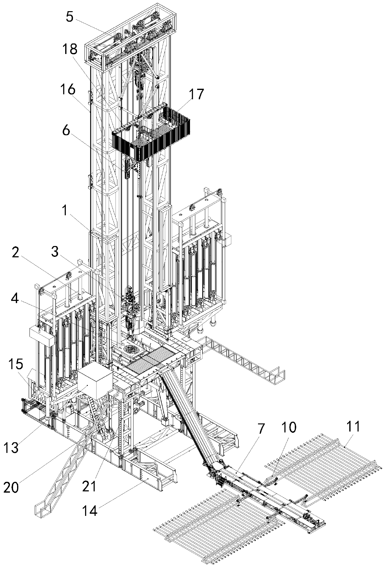
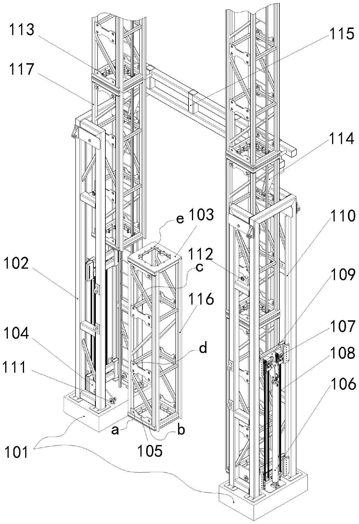
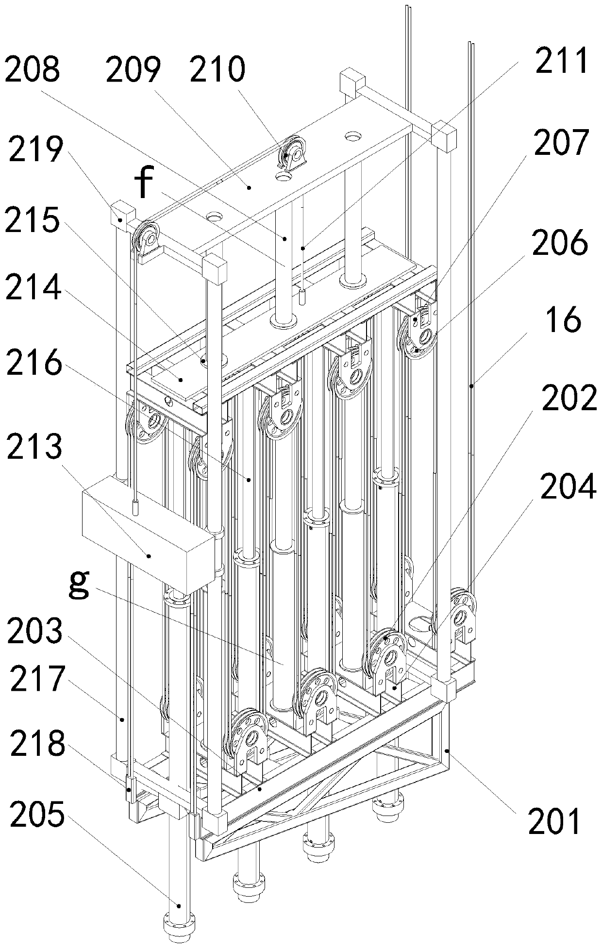
[0047] Such as Figure 1 to Figure 10 As shown, the fully hydraulic deep well drilling rig provided by the present invention includes a drilling tower, a main hydraulic lifting device 2, a hydraulic top drive drilling device 3, a continuous mud circulation device 4, a hydraulic automatic pipe arrangement machine 6, a hydraulic platform drilling tool transportation device 7, Comprehensive hydraulic station 8, drilling rig electrical control system, hydraulic iron driller 12 and reserve hydraulic energy 15, drilling tower, main hydraulic lifting device 2, hydraulic top drive drilling device 3, mud...


PUM


Abstract

A full-hydraulic deep well drilling machine includes a drill tower, a main hydraulic lifting device, a hydraulic top drive drilling device, a slurry continuous circulation device, a hydraulic automatic pipe arranging machine, a hydraulic platform drilling tool conveying device, a comprehensive hydraulic station, a drilling machine electrical control system, a hydraulic iron drill and a hydraulic energy reservation unit. The drill tower, the main hydraulic lifting device, the hydraulic top drive drilling device, the slurry continuous circulation device, the hydraulic automatic pipe arranging machine, the hydraulic platform drilling tool conveying device, the comprehensive hydraulic station, the hydraulic iron drill and the hydraulic energy reservation unit are each provided with a follow-upPLC, and all the PLCs and a main control PLC control system in the drilling machine electric control system are connected to a bus and are in communication connection with one another. The whole full-hydraulic deep well drilling machine is constructed by adopting an advanced electromechanical-hydraulic integrated technology, and has the advantages of being high in automation degree, high in control precision, stable and reliable in operation and convenient for realization of high-power integrated intelligent control.

Description

technical field [0001] The invention relates to a fully hydraulic deep well drilling rig, which belongs to the application field of exploration drilling and production construction such as oil and gas wells, geothermal wells and deep detection wells. Background technique [0002] Deep well drilling rig is an important equipment for exploring or drilling deep resources in the earth's crust and obtaining deep underground information. The main application fields of deep well drilling rigs involve oil and gas drilling, geothermal resource development, deep core drilling, etc. The main drive of traditional deep well drilling rigs usually consists of a hoisting winch and a turntable. Among them, the hoisting winch provides a single-strand steel rope to bypass the fixed pulley block of the crown block and the movable pulley block of the traveling block to form a mixed or parallel threading system, thereby forming a pulley multiplier mechanism to meet the hook load required for lif...

Claims


Application Information

Patent Timeline
Patent Type & Authority Applications(China)
IPC IPC(8): E21B3/02E21B15/00E21B19/00E21B19/14E21B21/00E21B44/00E21B19/16B66C11/22
Inventor 王清岩
Owner JILIN UNIV
Why Eureka
Try Eureka