Eureka AIR delivers breakthrough ideas for toughest innovation challenges, trusted by R&D personnel around the world.

Compact catadioptric type athermalization imaging spectrometer

An imaging spectrometer and catadioptric technology, which is applied in the field of spectral imaging, can solve the problem that large relative aperture, long slit and compact structure cannot be satisfied at the same time, and cannot meet the application requirements of large field of view, high signal-to-noise ratio and hyperspectral remote sensing, and the performance of spectrometer. Affected by temperature changes and other problems, to achieve the effect of reducing production and development costs, compact structure, and maintaining stable image quality

Active Publication Date: 2019-05-21
SUZHOU UNIV
View PDF6 Cites 6 Cited by
  • Summary
  • Abstract
  • Description
  • Claims
  • Application Information

AI Technical Summary

Problems solved by technology

[0005] In the imaging spectrometers reported in the existing literature, large relative apertures, long slits, and compact structures usually cannot meet the requirements simultaneously.
See literature "Design of Small Offner Spectral Imaging System" ( [J]. Optics Precision Engineering, 2005, 13(6):650) and "Design Method of Offner Imaging Spectrometer" ( [J]. Acta Optics Sinica, 2010 (4 ): 1148-1152), reported the traditional short and medium slit convex grating Offner device, which is a total reflection structure, and the slit length is less than 20mm; the literature "Research progress of Dyson optical system in infrared imaging spectrum measurement" ([J]. Science and Spectral Analysis, 2012, 32(2): 548-552), the concave grating Dyson device is a catadioptric imaging spectrometer, which can obtain a large relative aperture, but the slit is short, and it is difficult to be longer than 20mm, and this The performance of this spectrometer is greatly affected by temperature changes; Chinese invention patent CN102183304B "Optical path structure of a cylindrical astigmatism-eliminated grating dispersive imaging spectrometer" and the document "Research on aberration correction of a space-borne Czerny-Turner imaging spectrometer" ([J]. Acta Optics Sinica, 2009, 29(1): 35-40) The planar grating Czerny-Turner device is also a total reflection structure, but its slit length is very short and the relative aperture is small, so it cannot Meet the requirements of hyperspectral remote sensing applications with large field of view and high signal-to-noise ratio

Method used


Image

  • Compact catadioptric type athermalization imaging spectrometer
  • Compact catadioptric type athermalization imaging spectrometer
  • Compact catadioptric type athermalization imaging spectrometer

Examples


Embodiment 1

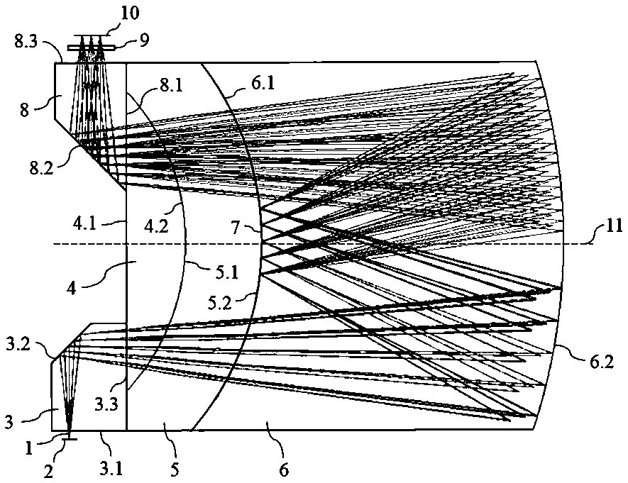
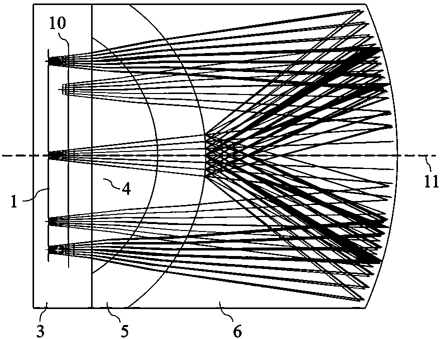
[0037] See attached figure 1 and 2, which are the front view of the optical path and the top view of the optical path of the compact reentrant athermal imaging spectrometer provided in this embodiment; the imaging spectrometer includes an incident slit 2, an object prism 3, a plano-convex lens 4, a meniscus lens 5, and a Mirror 6, convex grating 7, image square prism 8, optical filter 9 and focal plane 10, 3.1 is the incident surface of the object prism, 3.2 is the reflection surface of the object prism, and 3.3 is the exit of the object prism 4.1 is the plano-convex lens plane, 4.2 is the convex surface of the plano-convex lens; 5.1 is the concave surface of the meniscus lens, 5.2 is the convex surface of the meniscus lens; 6.1 is the concave surface of the thick fold mirror, 6.2 is the convex surface of the thick fold mirror; 8.1 is the incident surface of the image square prism, 8.2 is the reflection surface of the image square prism, and 8.3 is the exit surface of the ima...

Embodiment 2

[0052] See attached Figure 7 , which is the optical system when the grating of the compact reentrant athermalized imaging spectrometer provided in this embodiment is located on the convex surface of the plano-convex lens. It includes an entrance slit 2, an object prism 3, a plano-convex lens 4, a meniscus lens 5, a thick folding mirror 6, a convex grating 27, an image square prism 8, an optical filter 9 and a focal plane 10, as described in 3.1 The incident surface of the object prism, 3.2 is the reflective surface of the object prism, 3.3 is the exit surface of the object prism; 4.1 is the plano-convex lens plane, 4.2 is the convex surface of the plano-convex lens; 5.1 is the concave surface of the meniscus lens, and 5.2 is the meniscus lens The convex surface of the moon lens; 6.1 is the concave surface of the thick catadioptric mirror, 6.2 is the convex surface of the thick catadioptric prism; 8.1 is the incident surface of the image square prism, 8.2 is the reflection sur...


PUM


Abstract

The invention discloses a compact catadioptric type athermalization imaging spectrometer. Telecentric light incident from the slit is folded or refracted into a plano-convex lens by an object space prism; after being refracted by the plano-convex lens and a meniscus lens and refracted and reflected by a thick catadioptric mirror, the light beams are incident on a convex grating in the form of convergent light beams, and spectral light splitting is realized after diffraction; the divergent beams are refracted by the thick catadioptric mirror, the meniscus lens and the plano-convex lens in sequence and enter an image space prism; after being folded or refracted and filtered, the light is imaged on a focal plane to realize spectral imaging. According to the invention, the full-immersion catadioptric type optical path based on the Offner device is adopted, so that the structure is compact, and the relative aperture of the imaging spectrometer is greatly improved; the meniscus lens with a high refractive index is adopted to realize spectral imaging of a long slit; the thermal expansion coefficient of each refraction element material is optimized, so that the imaging spectrometer is stable in image quality within a large temperature range, and athermalization is realized; and the method is suitable for the hyperspectral remote sensing application with large view field, high signal-to-noise ratio and high temperature adaptability.

Description

technical field [0001] The invention relates to a compact catadioptric athermalization imaging spectrometer suitable for large field of view, high signal-to-noise ratio and high temperature adaptability, and belongs to the technical field of spectral imaging. technical background [0002] Spectral imaging technology is an emerging field that combines spectral spectroscopic technology and space imaging technology. It has greatly broadened the application scope of people in the field of aerospace remote sensing, agricultural and forestry resource detection, mineral resource and geological exploration, and military detectives. [0003] The traditional structural forms of dispersive imaging spectrometers mainly include: planar grating C-T type, convex grating Offner type, concave grating Dyson type, etc. The spectrometers with these structural forms have better performance in the case of short and medium slits and medium relative apertures, but in the case of long slits and larg...

Claims


Application Information

Patent Timeline
Patent Type & Authority Applications(China)
IPC IPC(8): G01J3/42
CPCG01J3/18G02B17/0808G02B13/22G01J3/0208G01J3/021G01J3/0216G01J3/0256G01J3/14G01J3/2823G01J2003/1208
Inventor 朱嘉诚沈为民
Owner SUZHOU UNIV
Why Eureka
Eureka Blog
Learn More