Power Devices and Appliances

A power device and circuit technology, which is applied in the field of electrical appliances with the power device, can solve the problems of increased power consumption of intelligent power modules, mixing materials, increasing the cost of intelligent power modules, etc., and achieve the effect of reducing material costs and facilitating material organization

Active Publication Date: 2020-06-05
GD MIDEA AIR-CONDITIONING EQUIP CO LTD +1
View PDF6 Cites 0 Cited by
  • Summary
  • Abstract
  • Description
  • Claims
  • Application Information

AI Technical Summary

Problems solved by technology

Replacing Si devices with SiC devices is an effective way to reduce the power consumption of intelligent power modules, but it also brings new problems because the threshold voltages of SiC devices and Si devices are different. Generally speaking, the threshold voltage of SiC devices is higher than that of Si devices. If Si devices are driven by the same high-voltage integrated circuit, the conduction process of SiC devices will inevitably be incomplete, and the advantages of SiC's low power consumption will not be brought into play, or even have the opposite effect. However, if different high-voltage Driven by integrated circuits, it will cause difficulties in the organization of materials in the production process, and there is a risk of mixing materials, which also increases the cost of intelligent power modules accordingly
Moreover, if the high-voltage integrated circuit driving the SiC device uses a higher voltage for power supply, it will inevitably increase the power consumption of the entire intelligent power module, which will offset the power reduction of the SiC device and reduce the power reduction of the intelligent power module using the SiC device. consumption effect
If a higher voltage is used to supply power to high-voltage integrated circuits that drive SiC devices, the peripheral electrical control scheme must be modified, which undoubtedly increases the resistance to intelligent power modules equipped with SiC devices

Method used


Image

  • Power Devices and Appliances
  • Power Devices and Appliances
  • Power Devices and Appliances

Examples


Embodiment Construction

[0027] Embodiments of the present application will be further described below in conjunction with the accompanying drawings. The same or similar reference numerals in the drawings represent the same or similar elements or elements having the same or similar functions throughout.

[0028] In addition, the embodiments of the present application described below in conjunction with the accompanying drawings are exemplary, and are only used to explain the embodiments of the present application, and should not be construed as limiting the present application.

[0029] In the present application, unless otherwise clearly specified and limited, a first feature being "on" or "under" a second feature may mean that the first and second features are in direct contact, or that the first and second features are indirect through an intermediary. touch. Moreover, "above", "above" and "above" the first feature on the second feature may mean that the first feature is directly above or obliquel...


PUM


Abstract

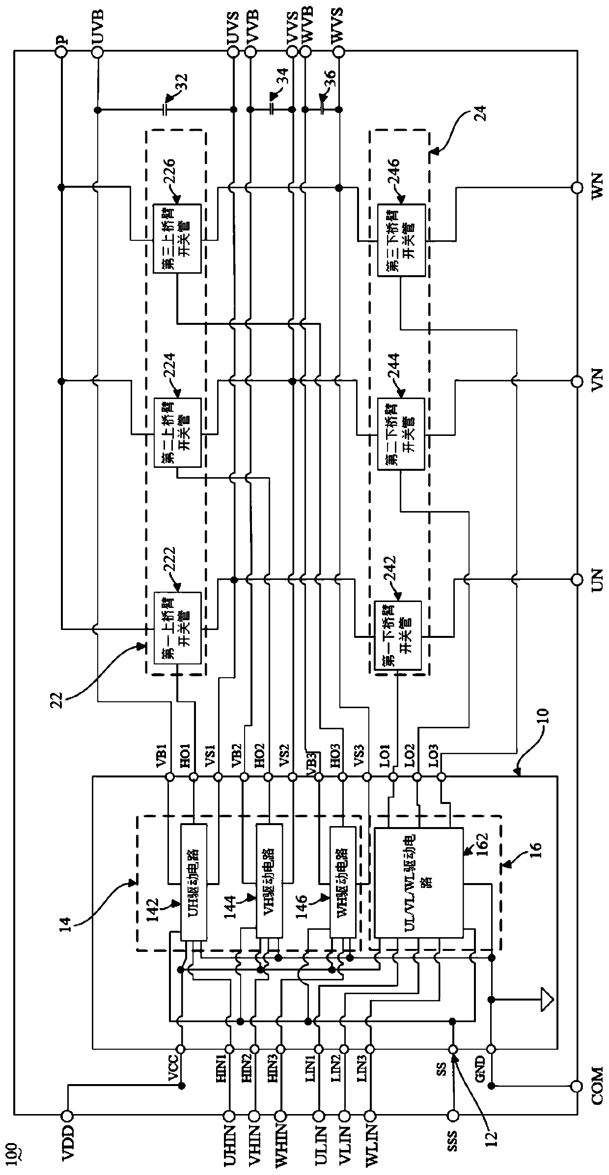
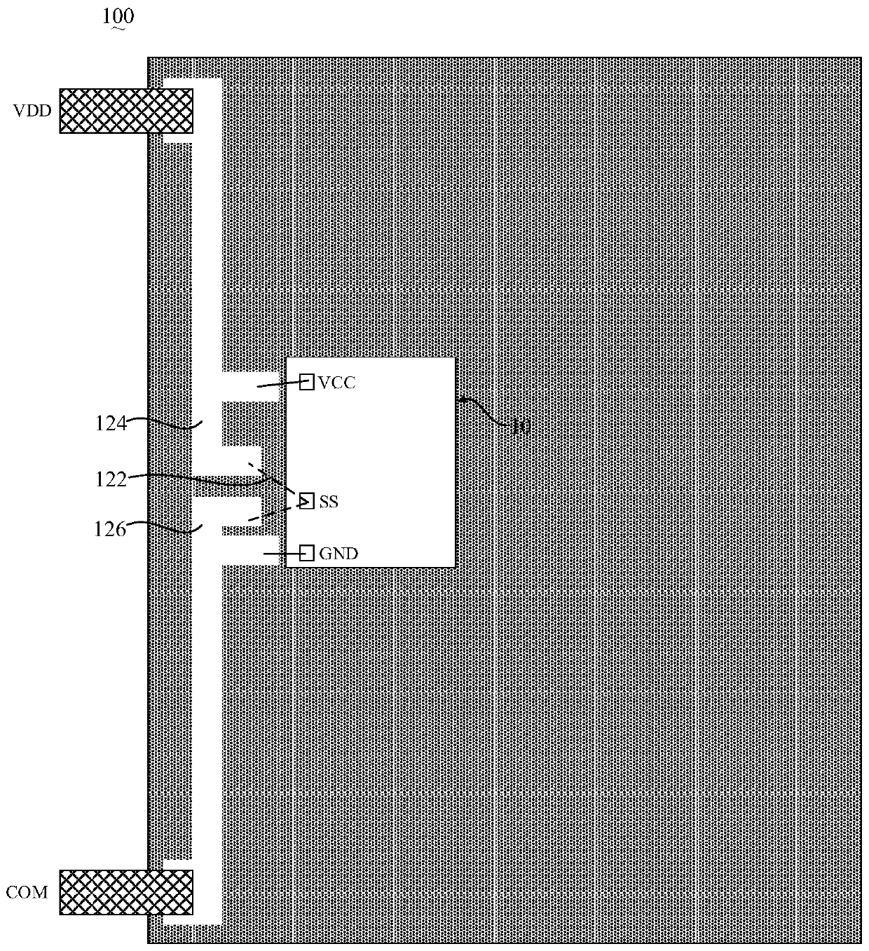
The present application discloses a power device and an electrical appliance, wherein the power device includes: a control input terminal, a switch tube of the upper bridge arm and a switch tube of the lower bridge arm, and a first drive circuit connected to the control input terminal and used to drive the switch tube of the upper bridge arm , a second drive circuit connected to the control input end and used to drive the switch tube of the lower bridge arm. The control input terminal can be connected to low level or high level. When the control input terminal inputs low level, the first drive circuit and the second drive circuit output high and low level signals in the first voltage range; Normally, the first driving circuit and the second driving circuit output high and low level signals in a second voltage range, and the first voltage range is different from the second voltage range. The power device of the present application can improve the adaptability of the silicon intelligent power module and the silicon carbide intelligent power module, so that the performance of the silicon intelligent power module and the silicon carbide intelligent power module can be brought into play.

Description

technical field [0001] The present application relates to the technical field of electric appliances, in particular to a power device and an electric appliance with the power device. Background technique [0002] Intelligent Power Module (IPM) is a power drive product (power device) that combines power electronics and integrated circuit technology. The intelligent power module integrates power switching devices (such as SiC (silicon carbide) devices or Si (silicon) devices) and high voltage integrated circuits (High Voltage Integrated Circuit, HVIC), and has built-in overvoltage, overcurrent and overheating, etc. fault detection circuit. On the one hand, the intelligent power module receives the control signal from the Micro Controller Unit (MCU) to drive the subsequent circuits to work, and on the other hand, it sends the system status detection signal back to the MCU. Compared with traditional discrete solutions, intelligent power modules have won an increasing market du...

Claims


Application Information

Patent Timeline
Patent Type & Authority Patents(China)
IPC IPC(8): H02M1/088
CPCH02M1/088H02M7/53873H02M7/53871H02M7/003H03K17/063H03K2217/0036Y02B70/10H03K17/6871H03K17/693
Inventor 冯宇翔
Owner GD MIDEA AIR-CONDITIONING EQUIP CO LTD
Why Eureka
Try Eureka