Distributed optical fiber loss measurement system based on Raman scattering and measurement method thereof
A distributed optical fiber and Raman scattering technology, applied in the field of optical fiber communication, can solve problems such as inaccurate measurement, more interference, and changes in reflected light intensity, and achieve the effect of improving accuracy
- Summary
- Abstract
- Description
- Claims
- Application Information
AI Technical Summary
Problems solved by technology
Method used
Image
Examples
Embodiment 1
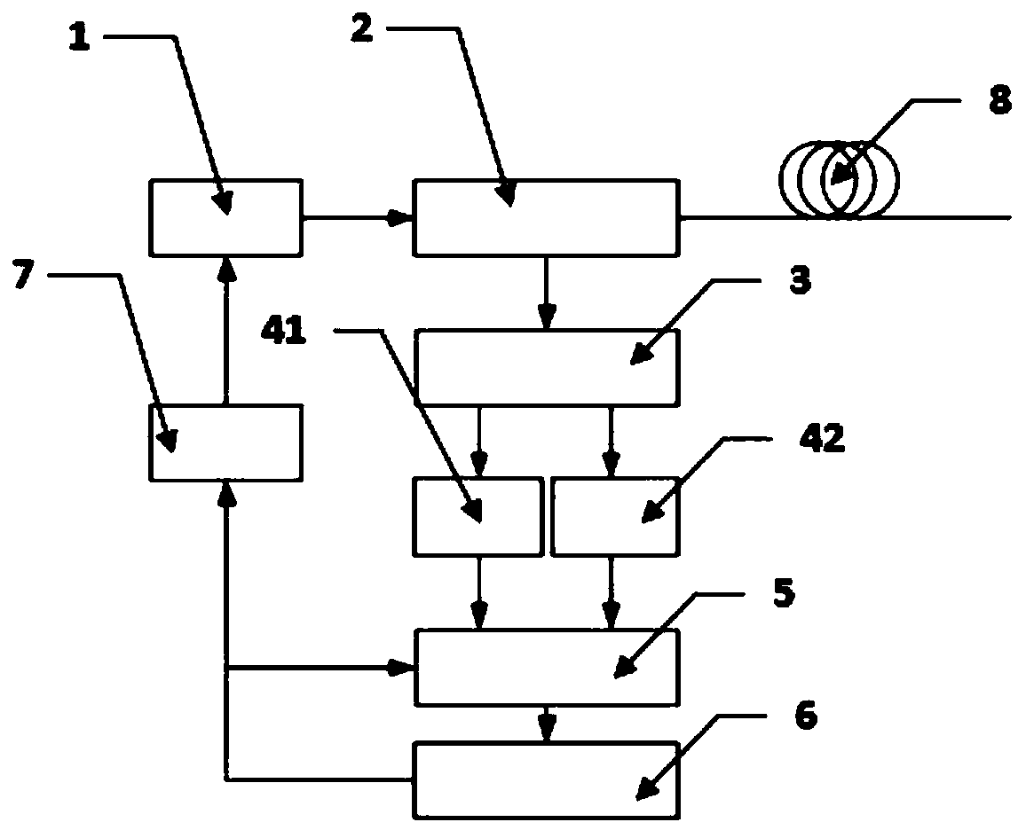
[0024] Such as figure 1 As shown, the distributed optical fiber loss measurement system based on Raman scattering, the measurement system is connected with the optical fiber to be detected, including a pulsed laser 1, a directional coupler 2, a beam splitter 3, a photodetector 41, a photodetector connected in sequence Device two 42, two-way high-speed signal collector 5, main control computer 6 and laser drive circuit 7, described laser drive circuit 7 is also connected with two-way high-speed signal collector 5 and pulse laser 1, and described optical fiber 8 to be detected is connected with The directional coupler 2 is connected, the main control computer 6 controls the laser drive circuit 7, the photodetector one 41 detects the Stokes light reflected back by the optical fiber 8 to be detected through Raman scattering, and the photodetector 2 42 detects the anti-Stokes light reflected back by the optical fiber 8 to be detected through Raman scattering.
[0025] The repetiti...
Embodiment 2
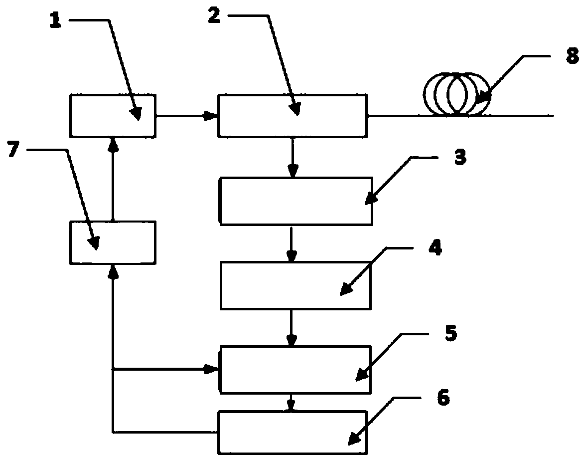
[0035] Such as figure 2 As shown, the distributed optical fiber loss measurement system based on Raman scattering, the measurement system is connected with the optical fiber to be detected, including a pulsed laser 1, a directional coupler 2, a beam splitter 3, a photodetector 4, a single high-speed Signal collector 5, main control computer 6 and laser driver circuit 7, described laser driver circuit 7 is also connected with single-way high-speed signal collector 5 and pulsed laser 1, and described optical fiber 8 to be detected is connected with described directional coupler 2 , the main control computer 6 controls the laser drive circuit 7, and the photodetector 4 detects the Stokes light reflected back by the optical fiber 8 to be detected through Raman scattering.
[0036] The repetition frequency f of the pulse laser 1 satisfies the condition f 2.5km, the wavelength of the pulsed laser is 1550nm; the peak power of the pulsed laser 1 is also determined by the length of th...
PUM
| Property | Measurement | Unit |
|---|---|---|
| length | aaaaa | aaaaa |
| wavelength | aaaaa | aaaaa |
Abstract
Description
Claims
Application Information
 - R&D
- Intellectual Property
- Life Sciences
- Materials
- Tech Scout
- Unparalleled Data Quality
- Higher Quality Content
- 60% Fewer Hallucinations
Browse by: Latest US Patents, China's latest patents, Technical Efficacy Thesaurus, Application Domain, Technology Topic, Popular Technical Reports.
© 2025 PatSnap. All rights reserved.Legal|Privacy policy|Modern Slavery Act Transparency Statement|Sitemap|About US| Contact US: help@patsnap.com


