A solar cell dark field phase-locked thermal imaging layered micro-defect accurate characterization system and method

A technology of solar cells and thermal imaging, which is applied in image analysis, image data processing, instruments, etc., can solve problems such as the inability to obtain the difference of luminous signals on the front and rear surfaces, the inability of luminescent signals to pass through, and the depth information of defects, etc., so as to improve the detection ability and detection efficiency, high signal-to-noise ratio, and the effect of improving the signal-to-noise ratio

Active Publication Date: 2019-05-28
HARBIN INST OF TECH
View PDF7 Cites 0 Cited by
  • Summary
  • Abstract
  • Description
  • Claims
  • Application Information

AI Technical Summary

Problems solved by technology

Luminescence detection methods such as photoluminescence (PL) and electroluminescence (EL) can obtain intuitive solar cell images with high resolution, but these detection methods are integrated signals in the entire depth direction of the solar cell, while the luminescence signal The metal back contact layer cannot be penetrated, and the difference of the luminous signal of the front and rear surfaces cannot be obtained. Even if the position of the defect is displayed, the depth information of the defect cannot be obtained

Method used


Image

  • A solar cell dark field phase-locked thermal imaging layered micro-defect accurate characterization system and method
  • A solar cell dark field phase-locked thermal imaging layered micro-defect accurate characterization system and method
  • A solar cell dark field phase-locked thermal imaging layered micro-defect accurate characterization system and method

Examples


specific Embodiment approach 1

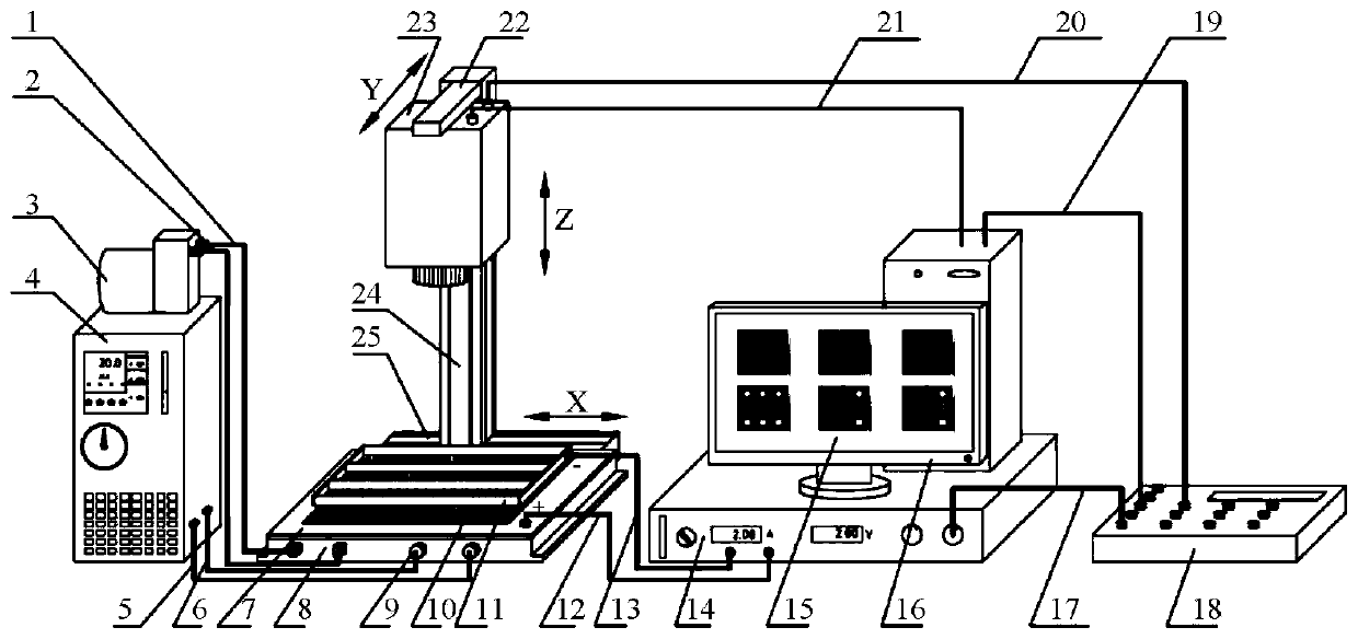
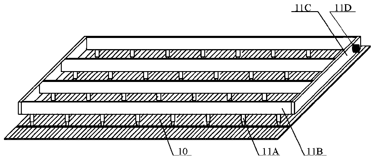
[0066] Specific implementation manner one: such as figure 1 As shown, the system for accurate characterization of solar cell stratification provided by this embodiment consists of suction hose 1, exhaust hose 2, vacuum pump 3, water-cooled pump 4, water inlet hose 5, drain hose 6, metal sample Station 7, vacuum adsorption device 8, water-cooled heat sink 9, silicon solar cell sample 10, sample fixture 11, DC power supply positive output line 12, DC power supply negative output line 13, DC power supply 14, solar cell defect layered accurate characterization It is composed of software 15, computer 16, first signal transmission line 17, data acquisition card 18, second signal transmission line 19, third signal transmission line 20, fourth signal transmission line 21, infrared thermal imager 23, and three-dimensional mobile platform. Among them:

[0067] The three-dimensional mobile platform is composed of a Y-direction mobile platform 22, a Z-direction mobile platform 24 and an X-dir...

specific Embodiment approach 2

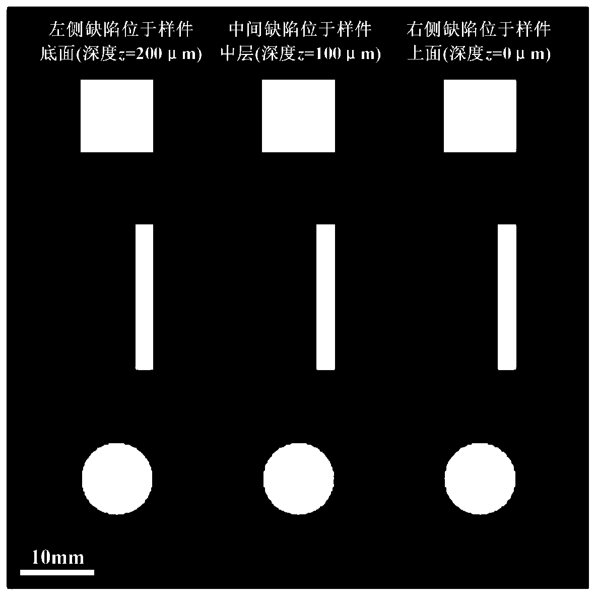
[0079] Embodiment 2: This embodiment provides a method for accurately characterizing the micro-defects of solar cells in layers using the system described in Embodiment 1. The method measures 0° images on the front and back surfaces of the solar cell sample. , -90° image, amplitude image and phase image, and the corresponding images are subtracted to obtain the defect depth resolution result of the solar cell sample. The specific implementation steps are as follows:

[0080] Step (1): Determine the silicon solar cell sample 10 to be measured, and place it on the metal sample table 7 with the front grid facing upward;

[0081] Step (2): Turn on the vacuum pump 3 and the water-cooled pump 4, place the sample fixture 11 on the grid of the silicon solar cell sample 10, fix the sample fixture 11 so that they are in good contact, and connect the positive output line 12 of the DC power supply to The metal sample table 7 is connected, and the negative output line 13 of the DC power supply...

specific Embodiment approach 3

[0089] Specific implementation manner 3: This implementation manner provides a layered and accurate characterization of solar cell defects using the system described in the first implementation manner. The method uses the point spread function (PSF) to obtain 0°, -90°, amplitude, and phase images are deconvolved to obtain real and imaginary images respectively. By changing the heat source depth z defined in the point spread function, until the deconvolved imaginary image is zero or reaches the minimum, this The depth z of the heat source in the point spread function at time is the actual depth of the solar cell defect, and the depth position of the heat source can be distinguished. It includes the following steps:

[0090] Step (1): Determine the silicon solar cell sample 10 to be measured, and place it on the metal sample table 7 with the front grid facing upward;

[0091] Step (2): Turn on the vacuum pump 3 and the water-cooled pump 4, place the sample fixture 11 on the grid of ...


PUM


Abstract

The invention discloses a solar cell dark field phase-locked thermal imaging layered micro-defect accurate characterization system and method. The system comprises a thermal infrared imager, a data acquisition card, a computer, a three-dimensional mobile station, a metal sample table, a water-cooling heat dissipation plate, a vacuum adsorption device, a sample clamp, a water-cooling pump, a vacuumpump and a direct-current power supply, wherein the thermal infrared imager and the water-cooling heat dissipation plate are arranged on the three-dimensional mobile station; the metal sample table and the vacuum adsorption device are arranged on the water-cooling heat dissipation plate; the water cooling heat dissipation plate is connected with the water cooling pump; the vacuum adsorption device is connected with a vacuum pump; the sample clamp is arranged on the metal sample table; the anode of the direct-current power supply is connected with the metal sample table, and the cathode is connected with the sample clamp; the thermal infrared imager is respectively connected with the computer and the data acquisition card; and the data acquisition card is respectively connected with the direct-current power supply and the computer. According to the method, the micro defects can be accurately characterized, and the method is a visual, accurate and large-area detection method.

Description

Technical field [0001] The invention belongs to the field of photovoltaic technology, and relates to a system and method for accurately characterizing layered micro-defects of solar cells based on the principle of dark-field phase-locked infrared thermal imaging. Background technique [0002] Solar cells are a key device for converting solar energy into electric energy and are widely used. Due to the complexity of its production process, various defects will inevitably occur in the production process. Common defects include printing defects, edge defects, sintering defects, and processing cracks. These defects will all lead to the reduction of the photoelectric conversion efficiency of the solar cell, which in turn affects its working efficiency. In severe cases, waste sheets may be produced, which reduces the working life of the solar cell module and causes irreversible economic losses. Therefore, related solar cell imaging and detection technologies have emerged, such as photo...

Claims


Application Information

Patent Timeline
IPC IPC(8): G06T7/00
Inventor 刘俊岩徐宏图宋鹏吴思萱王扬
Owner HARBIN INST OF TECH
Why Eureka
Try Eureka