Metallic composite material with high strength, high toughness and high magnetic performance and preparation of metallic composite material
A composite material, high-strength and high-toughness technology, applied in metal rolling, manufacturing tools, heat treatment equipment, etc., can solve the problems of poor safety and controllability of the preparation process, and achieve strong interface bonding, strong controllability, and safety The effect of high coefficient
- Summary
- Abstract
- Description
- Claims
- Application Information
AI Technical Summary
Problems solved by technology
Method used
Image
Examples
Embodiment 1
[0036] This embodiment provides a double-layer layered composite metal material, which is prepared through the following steps:
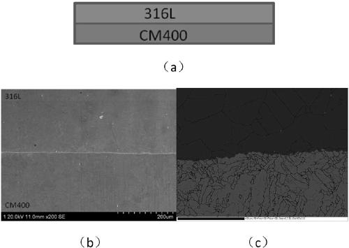
[0037] CM400 and 316L plates with a thickness of 2mm are used as original blanks, and the plates are cleaned and polished and stacked alternately as blanks (such as figure 2 as shown in a);
[0038] Put the stacked billets into the vacuum hot-press furnace, and evacuate to 10 -3 torr, and apply a preload pressure of about 2Mpa;
[0039] Raise the temperature to 1200°C at a rate of 10°C / S, apply pressure up to 30MPa, and keep the pressure for 15 minutes, unload, cool, and take out the billet;
[0040] The billet is cold-rolled, the rolling speed is 5m / min, the downforce is 5%, 1 pass;
[0041] Carry out heat treatment on the billet after rolling, the heat treatment process is: 820°C / 2h (air cooling) + 500°C / 4h (air cooling), thus obtaining ultra-high strength maraging steel / austenitic stainless steel layered metal composite material, the interfa...
Embodiment 2
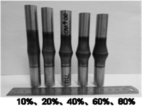
[0045] image 3 The rod-shaped layered composite metal material trial-produced in Example 1 was used to detect the interface bonding strength between the martensite layer and the austenite layer with different deformations.
[0046] It can be seen from Table 2 that the interfacial bonding strength of the hot-compressed state and the aged state is higher than that of the base metal, and both fracture on the austenite side.
Embodiment 3
[0048] Table 3 shows that the vacuum degree is 10 -1 Under torr, the interfacial bonding strength between the martensite layer and the austenite layer under different deformations of the bar-shaped layered composite metal material trial-produced according to Example 2.
[0049] It can be seen from Table 3 that the interfacial bond strength decreased significantly due to the decrease of vacuum degree.
[0050] Figure 4 and Figure 5 are the fracture morphology of the hot-pressed and peak-aged tensile samples under the condition of 20% deformation, respectively. It can be found that at the fracture position, that is, at the interface, due to the low vacuum, serious deformation occurs at the interface during the hot-pressing process. Oxidation phenomenon, resulting in a sharp decrease in interface strength.
PUM
 Abstract
Description
Claims
Application Information
 - R&D
- Intellectual Property
- Life Sciences
- Materials
- Tech Scout
- Unparalleled Data Quality
- Higher Quality Content
- 60% Fewer Hallucinations
Browse by: Latest US Patents, China's latest patents, Technical Efficacy Thesaurus, Application Domain, Technology Topic, Popular Technical Reports.
© 2025 PatSnap. All rights reserved.Legal|Privacy policy|Modern Slavery Act Transparency Statement|Sitemap|About US| Contact US: help@patsnap.com


