Centralized combustion device applied to internal heating type rotary furnace

A technology of a combustion device and a rotary furnace, which is applied in the field of boilers, can solve problems such as endangering physical and mental health, disease transmission, space pollution, etc., and achieve the effect of widespread use.

Pending Publication Date: 2019-06-07
山东金成环保科技有限公司
View PDF0 Cites 1 Cited by
  • Summary
  • Abstract
  • Description
  • Claims
  • Application Information

AI Technical Summary

Problems solved by technology

These wastes contain a large number of bacterial viruses, and have certain characteristics of space pollution, acute virus infection and latent infection. If management is not strengthened and discarded at will, it is easy to cause the spread of diseases and seriously endanger people's physical and mental health.
Combustible components account for 92% of the total weight of medical waste. At present, high-temperature incineration is the mainstream method to treat medical waste, but there are few incineration methods that can completely burn it and reduce secondary pollution.

Method used


Image

  • Centralized combustion device applied to internal heating type rotary furnace
  • Centralized combustion device applied to internal heating type rotary furnace
  • Centralized combustion device applied to internal heating type rotary furnace

Examples


Embodiment 1

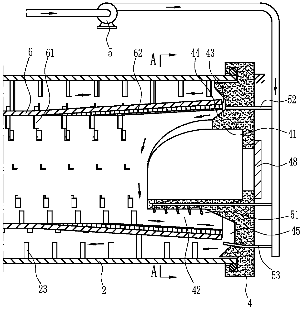
[0024] Embodiment one: if figure 1 and figure 2 As shown, the gathering combustion device for internal heating rotary furnace, this embodiment can burn and utilize raw materials containing mineral components such as lignite and oily soil, and the specific structure and principle of this embodiment will be described with oily soil.

[0025] This embodiment includes a furnace outer cylinder 2 and a furnace inner cylinder 6 which are rotated synchronously and arranged concentrically. The furnace outer cylinder 2 can be rotatably installed by a supporting wheel device and driven to rotate by an outer cylinder driving device. The end of the outer cylinder 2 of the furnace is dynamically sealed and connected with a gathering combustion end seat 4, and the dynamic sealing connection is a known technology, and will not be repeated here. The other end of the furnace outer cylinder 2 and the furnace inner cylinder 6 is also sealed and connected to the smoke exhaust port, slag discharg...

Embodiment 2

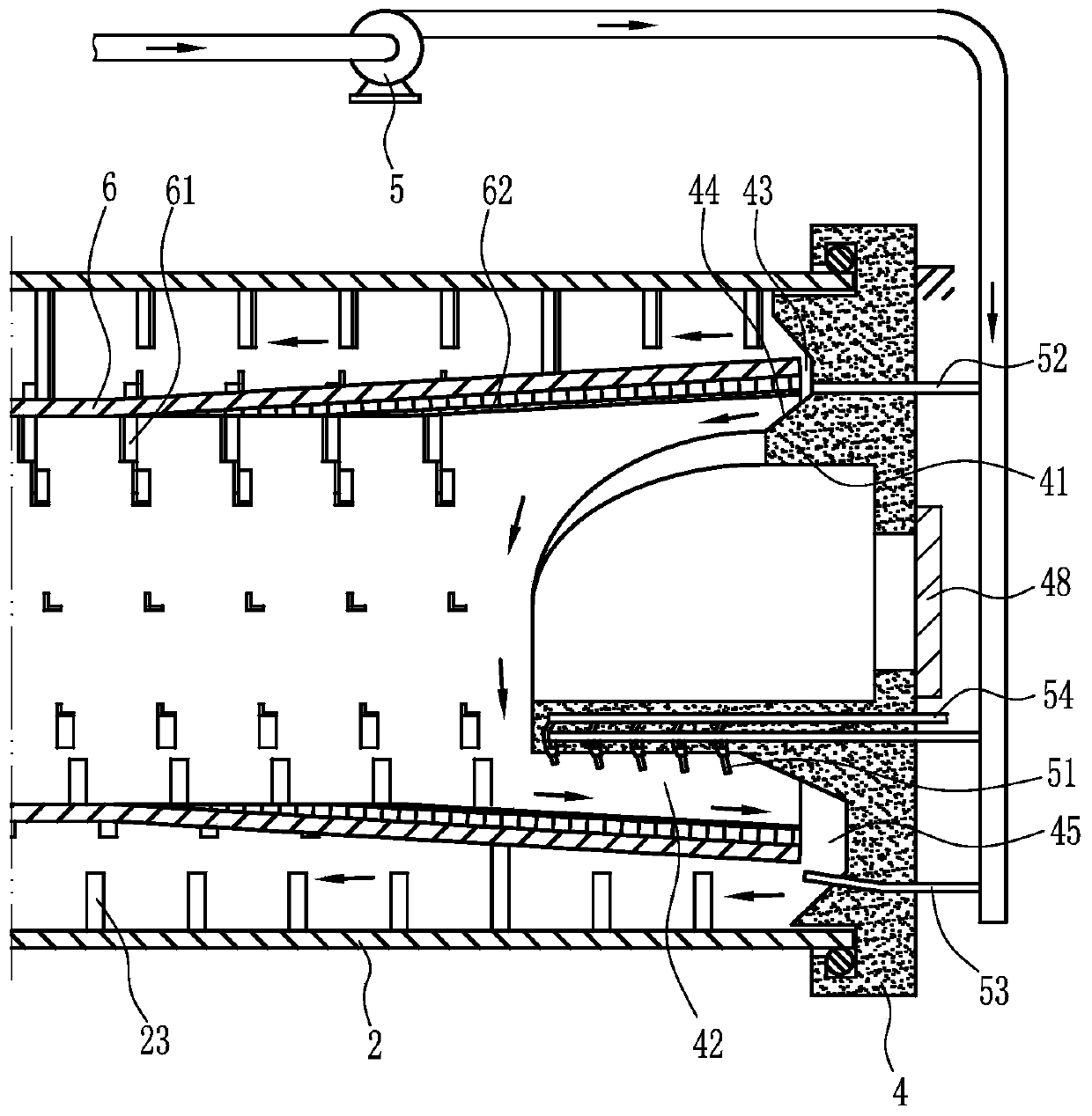
[0036] Embodiment two: if image 3 As shown, this embodiment can be used for industrial tail waste, such as boiler tail dust, organic sludge and other raw materials containing certain combustibles, for combustion and utilization. This embodiment uses the combustion of organic sludge to illustrate the specific structural principles.

[0037] The structure difference between this embodiment and Embodiment 1 is that the combustion-supporting air supply pipe 51 is connected with a natural gas supply device, and the known technology of supplying natural gas by the natural gas supply device will not be repeated here and only shown in the figure Natural gas supply pipe 54. This embodiment shows that the natural gas supply pipe 54 communicates with each of the combustion air supply pipes 51 through the branch pipes corresponding to the combustion air supply pipes 51 one by one, forming a mixed gas near the nozzle of the combustion air supply pipe 51 .

[0038] In this embodiment, th...

Embodiment 3

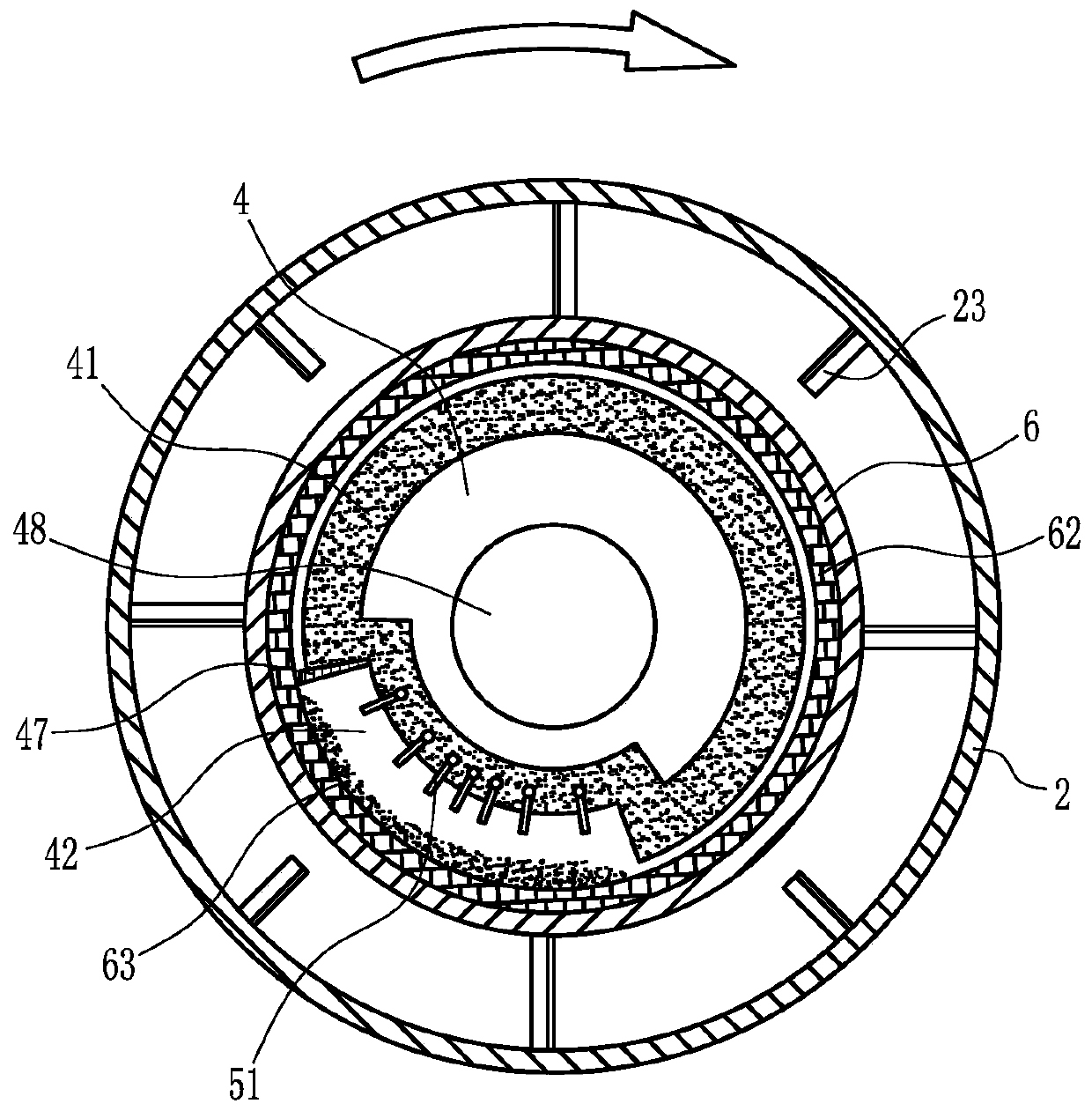
[0040] Embodiment three: as Figure 4 As shown, this embodiment can be used for the combustion and utilization of medical waste and even domestic waste. The structure of this embodiment when burning medical waste is the same as that of Embodiment 1, but its working principle is: the outer cylinder of the furnace 2 drives the inner cylinder of the furnace The cylinder 6 rotates synchronously, the combustion-supporting air supply pipe 51 continues to supply air, the isolation air pipe 52 keeps the air curtain isolated, and the furnace inner cylinder 6 forms a stable airflow to the furnace outer cylinder 2; medical waste is supplied to the The inner tube 6 of the furnace is gradually conveyed to the gathering and burning end seat 4 under the action of the inner tube pushing device 61. During this process, the medical waste is evenly heated by turning over the material, and part of the organic components can be cracked and gasified , the medical waste finally arrives at the gather...


PUM


Abstract

The invention discloses a centralized combustion device applied to an internal heating type rotary furnace. The centralized combustion device comprises a furnace outer cylinder and a furnace inner cylinder; an inner cylinder push device is arranged inside the furnace inner cylinder; an outer cylinder returning device is arranged inside the furnace outer cylinder; the end part of the furnace outercylinder is in dynamic tight coupling with a centralized combustion end base; the centralized combustion end base is provided with a combustion isolator which extends into the furnace inner cylinder;the combustion isolator is provided with a centralized combustion channel; a slag falling opening is arranged between the centralized combustion end base and the furnace inner cylinder; the centralized combustion channel is provided with a plurality of combustion-supporting air supply pipelines; an annular flame retardant coating is arranged inside the furnace inner cylinder; an air stop device isarranged between the centralized combustion end base and the furnace inner cylinder which is arranged outside a material collection region; and the furnace inner cylinder is connected with an air replenishing device. According to the centralized combustion device disclosed by the invention, a raw material can be preheated by adopting the combustion heat; organic components can be separated out, pyrolyzed and vaporized; by virtue of the air flow, gaseous combustible substances can reach the centralized combustion channel and are centralized so that centralized and violent combustion can be easily formed, thus sufficient combustion of residual combustible substances in the raw material can be promoted, and harmful substances contained in tail gases can also be obviously reduced.

Description

technical field [0001] The invention relates to the technical field of boilers, in particular to a gathering combustion device for an internal heating type rotary furnace. Background technique [0002] Crude oil will pollute the soil in the process of exploration, mining, transportation and storage. The physical and chemical properties of oil-bearing soil will change due to the presence of crude oil, and it will cause adverse effects on the human living environment on multiple levels through the pollution of groundwater and the transfer of pollution. coercion. The existence of oily soil not only affects the environment and restricts economic development, but also makes it difficult to reuse crude oil resources in the soil. [0003] Industrial tail waste refers to the solid waste and gas waste generated in the industrial production process, such as the tail dust filtered by the bag filter and the dried sludge of the sewage treatment plant. Based on the combustion technology...

Claims


Application Information

Patent Timeline
Patent Type & Authority Applications(China)
IPC IPC(8): F23G5/20F23G5/44F23G5/027F23G7/14F23G5/14
Inventor 刘振亮刘庆庆杨乐强
Owner 山东金成环保科技有限公司
Why Eureka
Try Eureka