A high-speed grid driving unit and a circuit
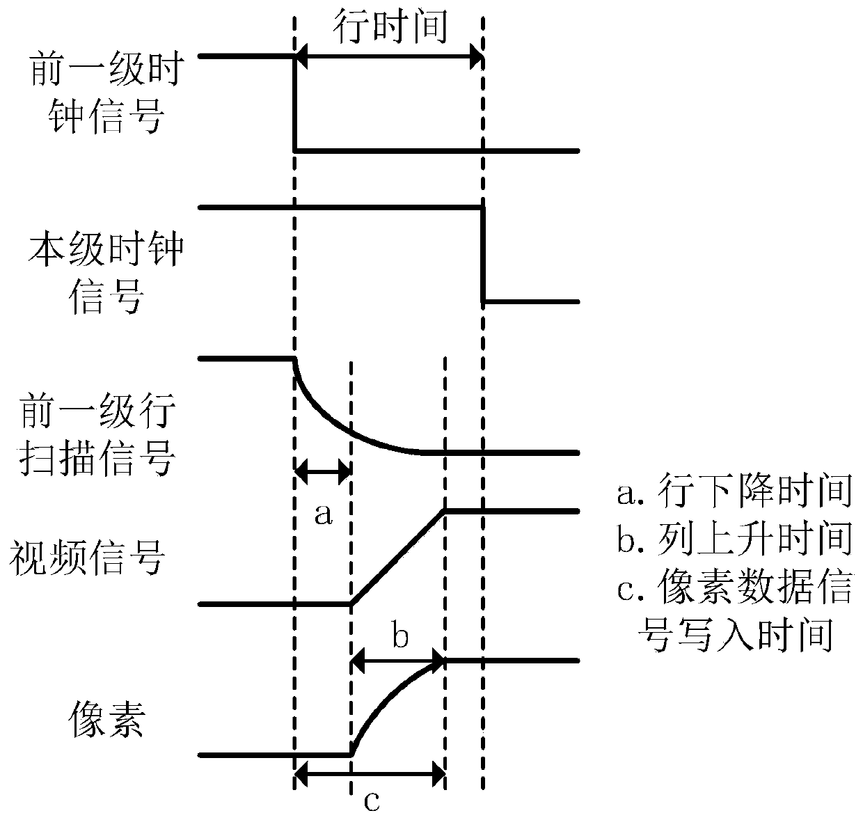
A gate-driven, high-speed technology, applied in the direction of static indicators, instruments, etc., can solve the problems of accelerating the output fall time, shortening the line time, increasing the load, etc., to save area, reduce the fall time, and reduce the size of the drive tube Effect
- Summary
- Abstract
- Description
- Claims
- Application Information
AI Technical Summary
Problems solved by technology
Method used
Image
Examples
Embodiment 1
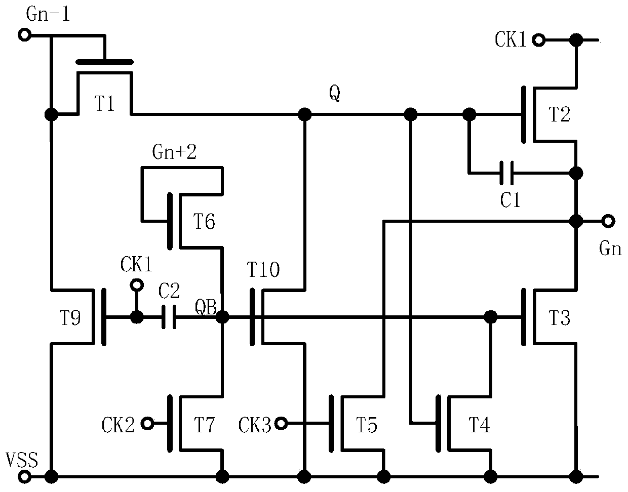
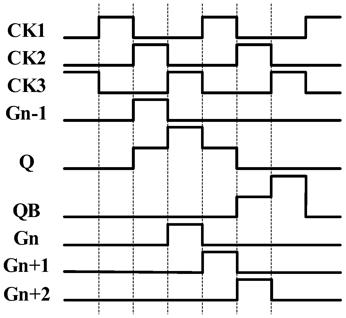
[0059] Please refer to Figure 4, is a schematic structural diagram of a high-speed gate driving unit disclosed in Embodiment 1 of the present invention. As shown in the figure, the high-speed gate driving unit of the embodiment of the present invention includes an input and reset unit 10 , an inverter unit 20 , a down-coupling unit 30 , an output driving unit 40 and a low-level maintaining unit 50 . The input and reset unit 10 is configured to receive a first clock signal and a first input signal, and charge an internal node Q1 to a high potential through the first input signal when the first clock signal is at a high level, and then When the first input signal is at a low level, the internal node Q1 is reset to a low level by the first clock signal. The inverter unit 20 is used to generate the control signal of the low level maintaining unit 50 and the coupling signal of the down coupling unit 30, and receive the second clock signal during the falling phase of the scanning ...
Embodiment 2
[0070] Please refer to Figure 6 , on the basis of Embodiment 1, the high-speed gate drive unit of an embodiment further includes an up-coupling unit 60 and a cascade generation unit 70; the up-coupling unit 60 is used to couple the potential of a cascade signal to the internal node Q1 to increase the potential of the internal node Q1. The cascade generation unit 70 is configured to receive the third clock signal and output the cascade signal when the internal node Q1 is at a high potential, and accelerate the third clock signal to be high through the internal node Q1 whose potential is raised When the level is low, the pull-up of the cascaded signal is charged and / or the output amplitude of the cascaded signal is increased.
[0071] In the embodiment of the present invention, the cascade generation unit 70 receives the third clock signal and outputs the cascade signal when the internal node Q1 is at a high potential, and the cascade signal is outputted through the rising cou...
Embodiment 3
[0077] Please refer to Figure 8 ,exist Figure 7 Based on the above, the high-speed gate drive unit in one embodiment further includes an isolation unit 80 for isolating the influence of the internal node Q1 on the potential of the internal node Q2 when the potential of the internal node Q1 is lower than the potential of the internal node Q2 and / or, when the potential of the internal node Q1 is higher than the potential of the internal node Q2, charge the internal node Q2 through the internal node Q1 to increase the potential of the internal node Q2.
[0078] In the embodiment of the present invention, the isolation unit 80 is used to isolate the internal node Q1 and the internal node Q2, suppress the reverse current from the internal node Q2 to the internal node Q1, or suppress the reverse current from the internal node Q1 to the internal node Q2 reverse current, so that the potentials between the internal node Q1 and the internal node Q2 will not interfere with each other....
PUM
 Abstract
Description
Claims
Application Information
 - R&D
- Intellectual Property
- Life Sciences
- Materials
- Tech Scout
- Unparalleled Data Quality
- Higher Quality Content
- 60% Fewer Hallucinations
Browse by: Latest US Patents, China's latest patents, Technical Efficacy Thesaurus, Application Domain, Technology Topic, Popular Technical Reports.
© 2025 PatSnap. All rights reserved.Legal|Privacy policy|Modern Slavery Act Transparency Statement|Sitemap|About US| Contact US: help@patsnap.com


