
Pressure damage detector

A detector and pressure technology, applied in the field of medical devices, can solve problems that are unfavorable for patients to cure pressure injuries, provide effective treatment methods, analyze disadvantages in depth, and prolong recovery time, so as to avoid inaccurate collection of data and data. Accurate and shortened recovery time

Inactive Publication Date: 2019-06-11
THE FIRST PEOPLES HOSPITAL OF CHANGZHOU
View PDF0 Cites 2 Cited by
  • Summary
  • Abstract
  • Description
  • Claims
  • Application Information

AI Technical Summary

Problems solved by technology

[0003] For the treatment of patients with pressure injury, medical personnel generally need to know the injury depth of the patient's pressure injury site and distinguish the surface color of the patient's pressure injury site. Cutting with scissors or a scalpel will make the patient more painful and prolong the recovery time. Secondly, the surface color of the patient's pressure injury site is judged by naked eyes, which is more subjective, so the accuracy is poor. The above data are useful for medical staff. In-depth analysis in the later period is extremely unfavorable, and it is not conducive to providing effective treatment for patients with pressure injury symptoms. Therefore, a pressure injury detector is proposed

Method used


Image

  • Pressure damage detector
  • Pressure damage detector
  • Pressure damage detector

Examples


Embodiment 1

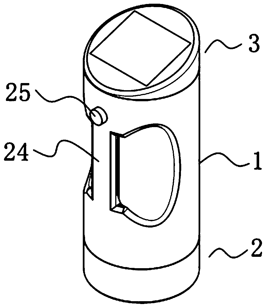
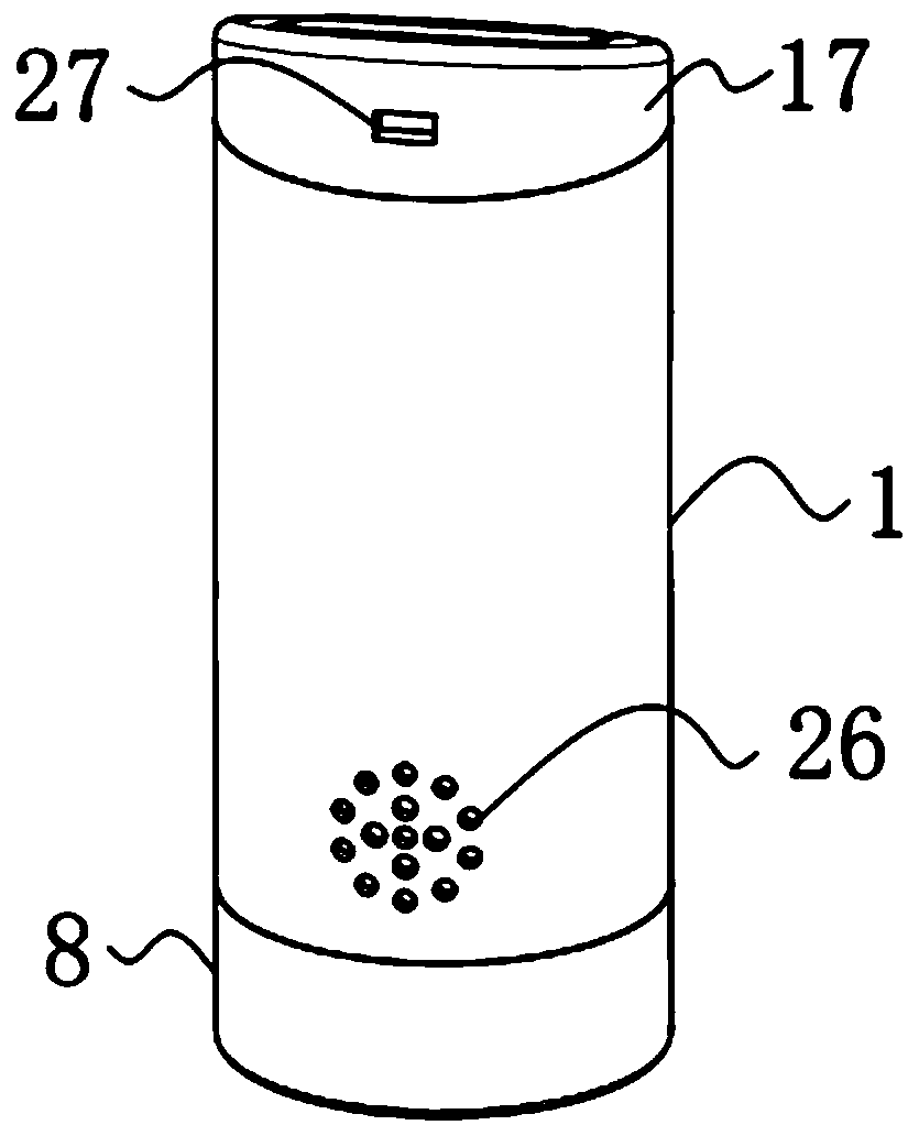
[0058] A pressure injury detector such as figure 1 , 5 As shown in and 7, it includes a cylindrical housing 1, the bottom end of the cylindrical housing 1 is provided with a detection part 2, and the upper end of the cylindrical housing 1 is provided with a display part 3, and the inside of the cylindrical housing 1 is also A control unit 5 is provided;

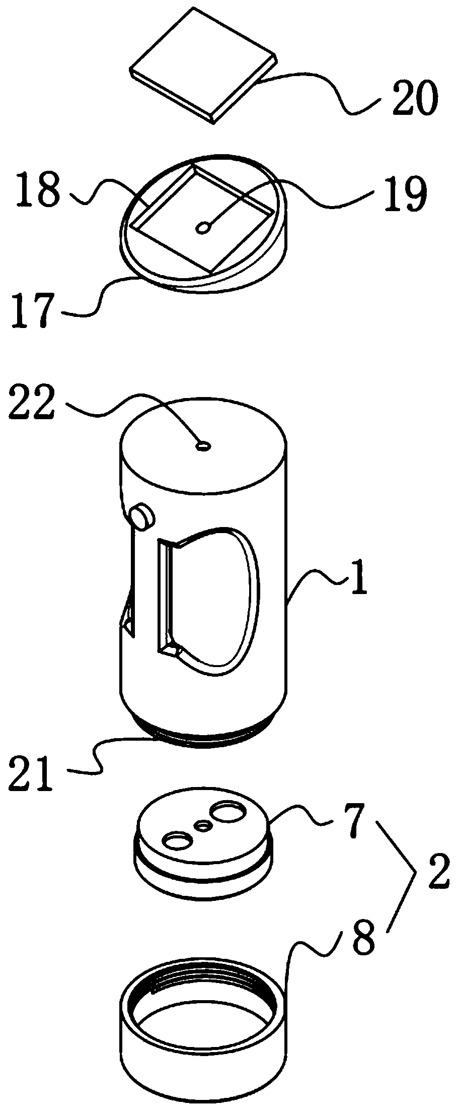
[0059] Such as image 3 , 9 As shown in and 10, the detection part 2 includes a transparent plexiglass end cover 8, a mounting base 7, an infrared detector 14 and a camera 12, and the transparent plexiglass end cover 8 is screwed to the bottom of the cylindrical shell 1 end, the mounting seat 7 is clamped on the bottom port of the cylindrical shell 1, and the mounting seat 7 is located inside the transparent plexiglass end cover 8, and the inside of the mounting seat 7 is provided with a second A mounting hole 11 and a second mounting hole 9, the infrared detector 14 is fixedly mounted inside the first mounting hole 11, a...

Embodiment 2

[0084] The difference from Example 1 is that a protective layer is also provided on the outer surface of the cylindrical shell 1, and the protective layer is prepared by the following method:

[0085] Take the following raw materials and weigh them by weight: 16 parts of epoxy resin, 18 parts of acrylic emulsion, 12 parts of copper oxide powder, 12 parts of nano-silver powder, 8 parts of titanium dioxide powder, 9 parts of calcium carbonate powder, 2 parts of alcohol ester twelve, three 3 parts of ethanolamine, 1 part of emulsified silicone oil and 30 parts of water;

[0086] S1. Add the weighed acrylic emulsion, alcohol ester dodeca, triethanolamine, emulsified silicone oil and water into the mixer and stir for 25min at a stirring speed of 600r / min to prepare a mixed solution;

[0087] S2, adding epoxy resin, copper oxide powder, nano-silver powder, titanium dioxide powder and calcium carbonate powder into a pulverizer for pulverization until the particle diameter of the mate...

Embodiment 3

[0093] The difference with embodiment 2 is the preparation of protective layer, and its specific preparation method is as follows:

[0094] Take the following raw materials and weigh them by weight: 19 parts of epoxy resin, 21 parts of acrylic emulsion, 14 parts of copper oxide powder, 14 parts of nano-silver powder, 10 parts of titanium dioxide powder, 11 parts of calcium carbonate powder, 3 parts of alcohol ester twelve, three 4 parts of ethanolamine, 2 parts of emulsified silicone oil and 40 parts of water;

[0095] S1. Add the weighed acrylic emulsion, alcohol ester dodeca, triethanolamine, emulsified silicone oil and water into the mixer and stir for 30min at a stirring speed of 650r / min to prepare a mixed solution;

[0096] S2, adding epoxy resin, copper oxide powder, nano-silver powder, titanium dioxide powder and calcium carbonate powder into a pulverizer for pulverization until the particle diameter of the material is not greater than 100nm to obtain a mixed powder ma...


PUM


Abstract

The invention discloses a pressure damage detector which comprises a cylindrical shell, a detection part is arranged at the bottom end of the cylindrical shell, a display part is arranged at the upperend of the cylindrical shell, and a control part is further arranged in the cylindrical shell. According to the invention, the damage depth of a pressure damage part of a patient can be detected, andthe surface color of the pressure damage part of the patient can be distinguished; and the data of the damage depth of the pressure damage part of the patient and the distinguishing data of the surface color of the pressure damage part of the patient can be displayed in real time, thus an accurate basis is provided for medical staff to diagnose the illness state of the patient, the medical staffcan conveniently judge the degree of the pressure damage of the patient, different treatment and nursing measures can be conveniently taken according to different damages, so that the rehabilitation time of the patient is shortened, detected and collected data of the detection part can be stored, deep analysis of the data in a later period is facilitated, medical staff can conveniently summarize work experience for pressure damage treatment, and an effective treatment means is provided for curing pressure damage diseases of the patient.

Description

technical field [0001] The invention relates to the technical field of medical instruments, more specifically, it relates to a pressure injury detector. Background technique [0002] A pressure injury is a localized injury to the skin and / or soft tissue over a bony prominence, medical or other device, and may appear as intact skin or an open sore, which may be painful. Injury is due to intense and / or prolonged pressure or pressure combined with shear. Soft tissue tolerance to pressure and shear may be influenced by microenvironment, nutrition, perfusion, comorbidities, and soft tissue condition. [0003] For the treatment of patients with pressure injury, medical personnel generally need to know the injury depth of the patient's pressure injury site and distinguish the surface color of the patient's pressure injury site. Cutting with scissors or a scalpel will make the patient more painful and prolong the recovery time. Secondly, the surface color of the patient's pressure...

Claims


Application Information

Patent Timeline
Patent Type & Authority Applications(China)
IPC IPC(8): A61B5/00
Inventor 张茹
Owner THE FIRST PEOPLES HOSPITAL OF CHANGZHOU
Learn More