
Method for carrying out electron beam/ion beam focusing etching and microscopic imaging on non-conductive substrate

A technology of ion beam focusing and microscopic imaging, which is applied in the direction of microstructure technology, microstructure devices, and manufacturing microstructure devices, etc., which can solve problems such as inconvenient research and application, blurred imaging, and unsatisfactory requirements

Active Publication Date: 2019-06-11
ZHEJIANG UNIV
View PDF10 Cites 0 Cited by
  • Summary
  • Abstract
  • Description
  • Claims
  • Application Information

AI Technical Summary

Problems solved by technology

[0004] Limited by the principles of the above two techniques, if the observed sample is a non-conductive material, charged ions or electrons are easy to accumulate on the surface of the sample, thereby interacting with the focused ion beam and interfering with the focusing effect of the electron beam / ion beam, making imaging Becomes blurred, unable to perform tasks such as focused ion beam etching and electron beam etching
[0005] Now there are silicon-silicon nitride substrates with windows, which can realize the observation of some non-conductive materials to a certain extent, but the substrate material of this method is limited and must have a certain thickness of silicon layer
At the same time, it can only be used to observe
If observation and micro-nano processing on different substrate materials are to be realized, the requirements cannot be met at all.
At present, the minimum resolution that can be processed on an insulating substrate without a conductive material support is greater than 80 nanometers, which greatly limits the application range of the two technologies of focused ion beam and electron beam etching, and also hinders the research and application of related fields. caused great inconvenience

Method used


Image

  • Method for carrying out electron beam/ion beam focusing etching and microscopic imaging on non-conductive substrate
  • Method for carrying out electron beam/ion beam focusing etching and microscopic imaging on non-conductive substrate
  • Method for carrying out electron beam/ion beam focusing etching and microscopic imaging on non-conductive substrate

Examples


Embodiment

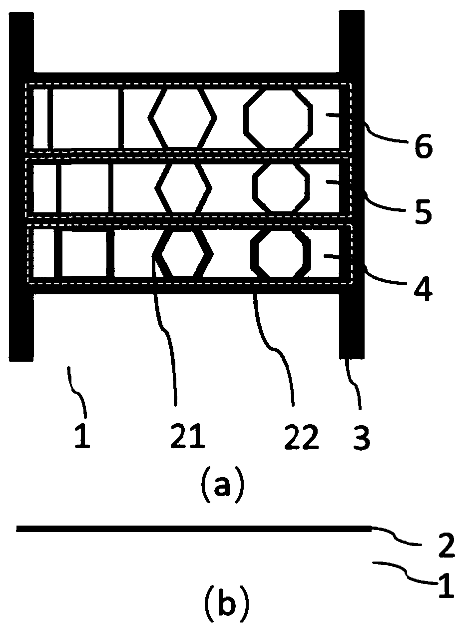
[0032] In this embodiment, the method for performing electron beam / ion beam focused etching and microscopic imaging on a non-conductive substrate includes the following steps:

[0033] S1 Design the shape and size of the photolithography mask;

[0034] S2 performing photolithographic treatment on the non-conductive substrate;

[0035] S3 performing metal coating treatment on the photolithographically processed non-conductive substrate to form a metal strip;

[0036] S4 develops the coated non-conductive substrate to become a sample;

[0037] S5 conducts grounding treatment on the metal belt;

[0038] S6 vacuumizes the sample;

[0039] S7 focuses on the metal strip of the sample, selects the electron beam current, and adjusts the sample stage to the sample area to be engraved after the imaging is clear;

[0040] S8 imports or draws the morphology of the micro-nano structure to be etched, and performs FIB or EBL etching and imaging on the sample after setting parameters.

...


PUM

PropertyMeasurementUnit
thicknessaaaaaaaaaa
thicknessaaaaaaaaaa

Abstract

The invention discloses a method for carrying out electron beam / ion beam focusing etching and microscopic imaging on a non-conductive substrate, and belongs to the field of micro-nano processing. Thecomprises the following steps of 1) designing the shape and size of a photoetching mask plate; 2) carrying out photoetching treatment on the non-conductive substrate; 3) carrying out metal coating treatment on the non-conductive substrate subjected to photoetching treatment to form a metal band; 4) carrying out developing treatment on the coated non-conductive substrate to form a sample; 5) grounding the metal strip; 6) vacuumizing the sample; 7) focusing the metal band of the sample, selecting an electron beam current, and adjusting the sample table to a sample area to be etched after imagingis clear; and 8) introducing or drawing the morphology of the micro-nano structure required to be etched, setting parameters, and performing FIB or EBL etching and imaging on the sample, thereby effectively improving the local electrical conductivity of the surface of the non-conductive substrate material, realizing the stable focusing of electron beams and ion beams, and further realizing the micro-nano etching and microscopic imaging on the surface of the non-conductive material.

Description

technical field [0001] The invention relates to the field of micro-nano processing, in particular to a method for performing electron beam / ion beam focused etching and microscopic imaging on a non-conductive substrate. Background technique [0002] Focused ion beam technology (focused ion beam, FIB) is a microdissection technology that uses electrostatic lenses to focus ion beams into very small sizes. Similarly, electron beam lithography (Electron-beam lithography, EBL) uses focused electron beams to expose the resist on the substrate to produce regions with different solubility properties in the resist. Dissolution properties, using a selective developer for development, to obtain the desired graphics. [0003] The above two technologies have important application value in the field of micro-nano processing. Principle comparison between focused ion beam microscope and scanning electron microscope, in which the ion beam is a liquid metal ion source (Liquid Metal Ion Sourc...

Claims


Application Information

Patent Timeline
Patent Type & Authority Applications(China)
IPC IPC(8): B81C1/00B81C99/00B82Y40/00
CPCB81C1/00349B81C1/00531B81C99/004B82Y40/00
Inventor 杨青庞陈雷张建培李竞曦汤明炜王伟刘旭
Owner ZHEJIANG UNIV
Learn More