
Solid waste treatment system adopting plasma gasification

A plasma and treatment system technology, applied in the field of plasma combustion devices, can solve the problems of poor waste gas treatment effect and reduced generation efficiency, so as to prevent secondary damage and improve work efficiency

Active Publication Date: 2019-06-14
泰州苏邦新能源技术有限公司
View PDF5 Cites 2 Cited by
  • Summary
  • Abstract
  • Description
  • Claims
  • Application Information

AI Technical Summary

Problems solved by technology

The incineration of fossil fuels has the following disadvantages: incomplete combustion will produce toxic and harmful gases such as dioxins, and incomplete combustion will produce a large amount of fly ash and a large amount of residue
The ash or waste slag generated during the combustion process at the above high temperature adheres to the furnace body. With long-term combustion, more and more ashes or waste slag are accumulated. or waste residue removal, reducing the generation efficiency
[0004] At the same time, although the introduction of harmless treatment of exhaust gas similar to wet dust removal exists in the prior art, the treatment of exhaust gas produced by the plasma gasification solid waste treatment system and containing long-chain nitrogen oxides The effect is still not good

Method used


Image

  • Solid waste treatment system adopting plasma gasification
  • Solid waste treatment system adopting plasma gasification
  • Solid waste treatment system adopting plasma gasification

Examples


Embodiment 1

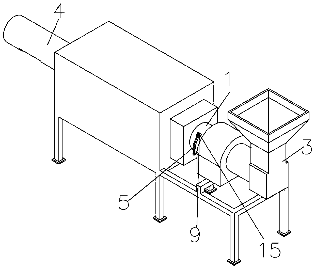
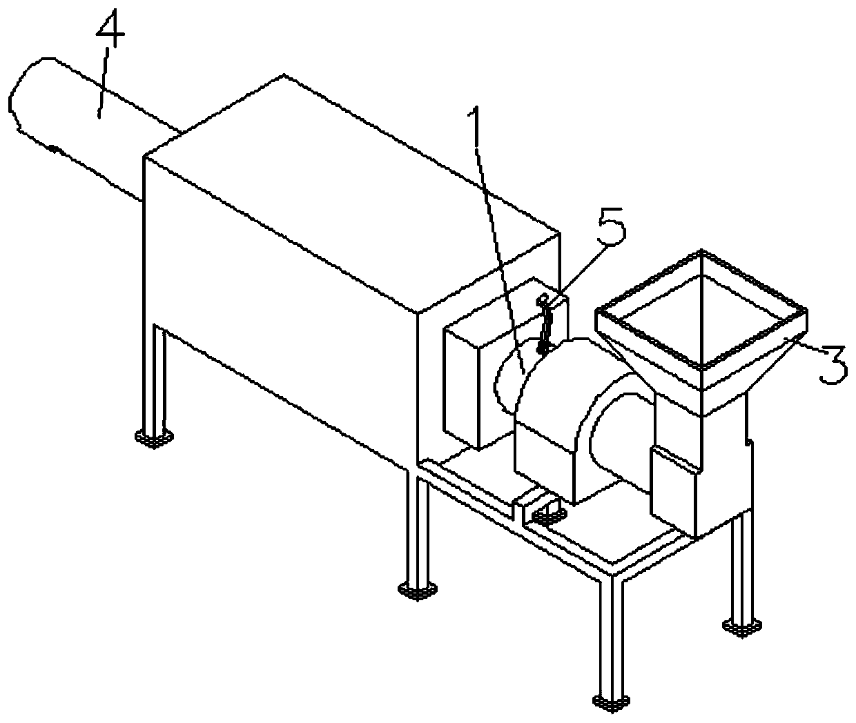
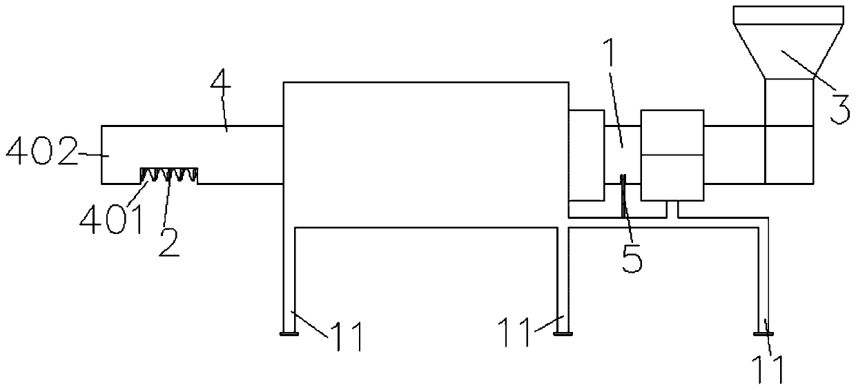
[0036] Such as Figure 1-8 As shown, a plasma gasification solid waste treatment system provided by the present invention includes a furnace body 1 and a drive assembly (not shown) that drives the furnace body 1 to rotate; specifically, the drive assembly can be a motor, etc., which can drive The furnace body 1 rotates; a charging device 3 located on one side of the furnace body 1 , and a discharge device 4 located on one side of the furnace body 1 . In this embodiment, the drive assembly can drive the furnace body 1 to rotate. When the furnace body 1 rotates, the ashes or solid waste on the inner wall of the furnace body 1 at the highest point of the worktable will automatically fall down by gravity, and some sticky Sticky ashes and solid waste cannot fall. The plasma gasification solid waste treatment system also includes a striking assembly 5, which is movably arranged on the furnace body 1, and the rotating furnace body 1 in the working state drives the striking assembly ...

Embodiment 2

[0042] As a further improvement of the above-mentioned embodiment, in this embodiment, during the cycle of one rotation of the furnace body 1, the beating assembly 5 passes the highest point at least once at a certain moment, and the above-mentioned highest point is the distance from the end of the beating assembly 5 The vertical distance of the furnace body is the farthest. In this embodiment, by setting the highest point, the falling height is high, and the gravity is large when knocking, which increases the removal of ash or waste residue in the furnace body 1; at the same time, after passing the highest point, it continues to rotate, and the striking assembly 5 falls by gravity. Hit the furnace body 1.

[0043] In the present embodiment, two striking assemblies 5 are arranged symmetrically, on the outer periphery of the furnace body 1 , two strikings can be realized each time. Certainly, there may be more striking assemblies 5 , which may be evenly distributed on the oute...

Embodiment 3

[0047] As a further improvement of the above embodiment, in this embodiment, the striking assembly 5 includes a striking hammer 6, a connecting rod 7 connected to the striking hammer 6, and a through hole 8 is provided at the end of the connecting rod 7; in this embodiment , a fixing seat 9 is provided on the outer surface of the furnace body 1, a connecting hole 15 matching the through hole 8 is arranged on the fixing seat 9, and a fastener (for example, the fastener can be configured as a bolt assembly, a rivet, etc.) Through the through hole 8 and the connecting hole 15, the striking assembly 5 and the fixing seat 9 can be rotatably assembled. Compared with Embodiment 1 and / or Embodiment 2, in this embodiment, the beating assembly 5 is movably connected to the fixed seat 9 through fasteners, etc., and the beating assembly 5 is loosely connected to the furnace body 1 , falling causes safety problems.

[0048] Further, refer to Figure 8 As shown, the connecting rod 7 inclu...


PUM


Abstract

The invention discloses a solid waste treatment system adopting plasma gasification. The solid waste treatment system adopting plasma gasification comprises a furnace body, a drive assembly driving the furnace body to self-rotate, a charge device located at one side of the furnace body, a discharge device located at one side of the furnace body, and a knocking assembly, wherein the knocking assembly is movably arranged on the furnace body, the furnace body self-rotating in a working state drives the knocking assembly to regularly knock the furnace body, and when the furnace body self-rotates by one cycle, the knocking assembly at least knocks once; and the discharge device is connected with a smoke treatment device. The solid waste treatment system adopting plasma gasification realizes continuous efficient incineration treatment on hazardous waste, is capable of synchronously removing ash or waste residue attached into the furnace body, and realizes efficient purification treatment onwaste gas which is in a high-temperature state, contains long-chain nitric oxides, and is generated by the solid waste treatment system adopting plasma gasification.

Description

technical field [0001] The invention relates to the technical field of plasma combustion devices, in particular to a plasma gasification solid waste treatment system. Background technique [0002] Traditional hazardous waste treatment methods include fossil fuel incineration and solidified landfill. The incineration of fossil fuels has the following disadvantages: incomplete combustion will produce toxic and harmful gases such as dioxins, and incomplete combustion will produce a large amount of fly ash and a large amount of residue. Because it has not been treated, under the long-term infiltration of rainwater and groundwater, it will cause pollution to the groundwater system and soil. [0003] Plasma hazardous waste incineration technology has unique advantages in hazardous waste treatment: plasma can generate high temperatures above 1700°C, hazardous waste is completely incinerated under the dual effects of high temperature and activation energy, inorganic solids become m...

Claims


Application Information

Patent Timeline
IPC IPC(8): F23G5/20F23G5/08F23G5/44F23J1/00F23J15/02B01D53/86B01D53/72B01D53/56
Inventor 刘彬殷林宝陆剑
Owner 泰州苏邦新能源技术有限公司
Learn More