

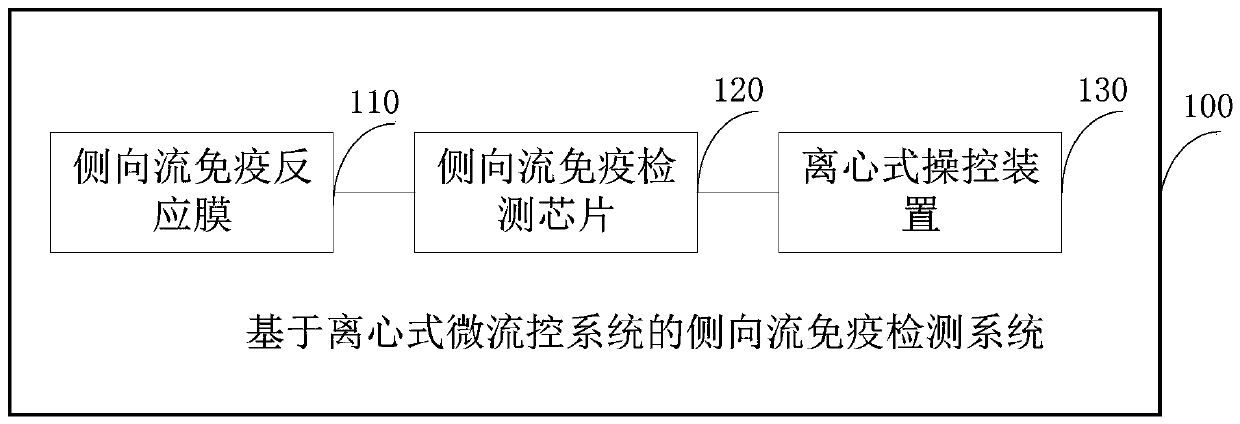
Lateral flow immune detection system based on centrifugal microfluidic system
An immunodetection, lateral flow technology, applied in the field of microfluidics, can solve the problems of limited volume, limited detection sensitivity, uncontrollable flow rate of reaction liquid, etc., and achieve the effect of improving sensitivity and high detection effect.
- Summary
- Abstract
- Description
- Claims
- Application Information
AI Technical Summary
Problems solved by technology
Method used
Image

Examples
Embodiment 1
[0054] Specifically, Example 1: Centrifugal microfluidic lateral flow immunoassay (condition 1)
[0055] Such as Figure 4 Shown is a schematic diagram of the chip structure in this embodiment. The first functional module consists of a first sample loading chamber 31, a first reaction chamber 32, a first reaction membrane cavity 33, a first waste liquid chamber 34, a first micropipe 35 and a first sample injection hole / vent hole 36. Before the chip is used, the freeze-dried reagent is stored in the first sample adding chamber 31, and then packaged with a single-sided glue. When in use, the solution to be tested and the buffer are mixed into the first sample loading chamber 31, and the chip is fixed on the chip tray 15. When the centrifuge rotates at a high speed, the reaction liquid enters the first reaction chamber 32 through the first micropipe 35 to contact the reaction membrane in the first reaction membrane cavity 33, reacts at 2000 rpm for 15 minutes (condition 1), and the...
Embodiment 2
[0061] Example 2: Centrifugal microfluidic lateral flow immunoassay (condition 2)
[0062] The operation before the reaction liquid contacts the reaction membrane is the same as in Example 1. When the reaction liquid contacts the reaction membrane, the reaction is completed at 1500 rpm for 45 minutes (condition 2), and the detection result is obtained through mobile phone imaging.
[0063] Further, in an embodiment of the present invention, the lateral flow immunoassay chip further includes a second functional module, wherein the second functional module is composed of a second sample chamber, a whole blood cell separation and quantification chamber, and a buffer solution. The sample chamber, the buffer transfer chamber, the first reagent freeze-drying chamber, the second reaction chamber, the second reaction membrane cavity, the second waste liquid chamber, the second micro-pipe and the second vent, are used for whole blood sample Preset sample processing and processing procedures...
Embodiment 3
[0064] Specifically, Example 3: Application of tumor marker detection in whole blood
[0065] Figure 7 It is a schematic diagram of the chip structure in this embodiment. The second functional module consists of a second sample chamber 41, a whole blood cell separation and quantification chamber 42, a buffer sample chamber 43, a buffer transfer chamber 44, a first reagent freeze-drying chamber 45, a second reaction chamber 46, The second reaction membrane cavity 47, the second waste liquid chamber 48, the second micro pipe 49 and the second vent 50 are composed. In use, the whole blood is added to the second sample adding chamber 41, the buffer is added to the buffer sample adding chamber 43, and the chip is fixed on the chip tray. When the centrifuge rotates at a high speed, the whole blood and buffer solution enter the downstream cavity along the microchannel 49a, respectively. During the process of high-speed centrifugation of whole blood, blood cells gradually settle to fu...
PUM
 Abstract
Description
Claims
Application Information