Optical fiber temperature signal automatic gain device and optical fiber temperature demodulator

An optical fiber temperature and automatic gain technology, used in thermometers, measuring devices, thermometers with physical/chemical changes, etc., can solve the problems of temperature information measurement error, not considering the influence of Stokes signal, etc., to eliminate differences, The effect of increasing precision

Active Publication Date: 2021-01-29
广州市纬桐晟安科技有限公司
View PDF5 Cites 0 Cited by
  • Summary
  • Abstract
  • Description
  • Claims
  • Application Information

AI Technical Summary

Problems solved by technology

[0003] In the demodulation process of the reflected laser signal reflected by the fiber, only the attenuation of the light by the fiber material, the attenuation caused by the microbend, the change of the injected light pulse power, and the difference in the response of the temperature measuring instrument to the light signal are considered. Temperature information measurement error, does not take into account the deviation between the Stokes signal and the anti-Stokes signal on the calculation of the temperature value

Method used


Image

  • Optical fiber temperature signal automatic gain device and optical fiber temperature demodulator
  • Optical fiber temperature signal automatic gain device and optical fiber temperature demodulator
  • Optical fiber temperature signal automatic gain device and optical fiber temperature demodulator

Examples


Embodiment 1

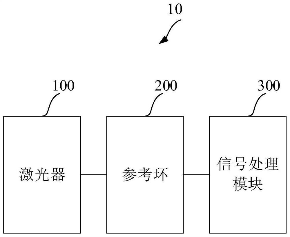
[0042] figure 1 A schematic structural diagram of an optical fiber temperature signal automatic gain device provided by the first embodiment of the present invention is shown.

[0043] The optical fiber temperature signal automatic gain device 10 includes a laser 100 , a reference ring 200 and a signal processing module 300 .

[0044] The laser 100, the reference ring 200 and the signal processing module 300 are connected in sequence.

[0045] The laser 100 is used to transmit laser signals to the optical fiber.

[0046] Specifically, the laser 100 emits a laser signal, and the laser signal is incident into an optical fiber whose temperature needs to be measured.

[0047] The reference ring 200 is connected with the laser for receiving the reflected laser signal returned from the optical fiber, and sending the reflected laser signal to the signal processing module 300 .

[0048] Specifically, when the laser signal propagates in the optical fiber, a part of the laser signal ...

Embodiment 2

[0081] Figure 4 A schematic structural diagram of an optical fiber temperature signal automatic gain device provided by the third embodiment of the present invention is shown.

[0082]The optical fiber temperature signal automatic gain device 10 includes a laser 100 , a reference ring 200 , a signal processing module 300 , a signal modulation module 400 and a signal amplification module 500 .

[0083] The signal modulation module 400 , the laser 100 , the reference ring 200 , the signal amplification module 500 and the signal processing module 300 are connected in sequence.

[0084] The signal modulation module 400 includes a power control unit 410 , a wavelength control unit 420 and a synchronization pulse unit 430 .

[0085] The power control unit 410 is used to send a power control signal to control the power of the laser signal sent by the laser 100, and the wavelength control unit 420 is used to send a wavelength control signal to control the wavelength of the laser sig...

Embodiment 3

[0093] Figure 5 A schematic structural diagram of an optical fiber temperature signal automatic gain device provided by the third embodiment of the present invention is shown.

[0094] The optical fiber temperature signal automatic gain device 10 includes a laser 100 , a reference ring 200 , a signal processing module 300 , a signal modulation module 400 , a signal amplification module 500 , a wavelength division multiplexing module 600 and an optical switch 700 .

[0095] The signal modulation module 400 is connected to the laser 100, the laser 100 is connected to the wavelength division multiplexing module 600, the wavelength division multiplexing module 600 is connected to the reference ring 200, and the reference ring 200 is connected to the optical A switch 700, the optical switch 700 is connected to a plurality of optical fibers for temperature measurement, such as Figure 5 A, B, C, D four optical fibers.

[0096] The wavelength division multiplexing module 600 is al...


PUM


Abstract

The invention discloses an optical fiber temperature signal automatic gain device and an optical fiber temperature demodulator. The device includes a laser, a reference ring and a signal processing module connected in sequence; the laser is used to transmit a laser signal to an optical fiber; It is used to receive the reflected laser signal returned from the optical fiber; the signal processing module is connected with the reference ring, and is used to determine the first current amplitude corresponding to the Stokes signal in the reflected laser signal and the second current corresponding to the anti-Stokes signal amplitude, and calculate the difference between the first current amplitude and the second current amplitude, and continuously adjust the corresponding photoelectric parameters according to the difference until the difference meets the predetermined condition. The technical scheme of the present invention eliminates the difference between the Stokes signal and the anti-Stokes signal in the Raman scattered photon signal, provides accurate basic data for accurate temperature measurement, realizes automatic gain adjustment, and enables different optical fibers to be connected The optimal measurement parameters can be obtained.

Description

technical field [0001] The invention relates to the technical field of optical fiber temperature measurement systems, in particular to an optical fiber temperature signal automatic gain device and an optical fiber temperature demodulator. Background technique [0002] In the existing fiber optic temperature measurement system based on the Raman scattering effect, since the Stokes signal and the anti-Stokes signal contain temperature-sensitive frequency components, for the fiber optic temperature measurement system, the Stokes The accuracy of the Stokes signal and the anti-Stokes signal is closely related to the accuracy of the calculated temperature. [0003] In the demodulation process of the reflected laser signal reflected by the fiber, only the attenuation of the light by the fiber material, the attenuation caused by the microbend, the change of the injected light pulse power, and the difference in the response of the temperature measuring instrument to the light signal ...

Claims


Application Information

Patent Timeline
Patent Type & Authority Patents(China)
IPC IPC(8): G01K11/32G01K11/322G01K11/324
Inventor 叶绍亮李陵花修犇梁海华
Owner 广州市纬桐晟安科技有限公司
Why Eureka
Try Eureka