
An arc electron source enhanced glow discharge surface activation process for PVD coating

A glow discharge and surface activation technology, which is applied in metal material coating process, sputtering coating, vacuum evaporation coating, etc., can solve the problems of rough and unsatisfactory workpiece surface, achieve high cleanliness, improve efficiency, The effect of reducing the risk of workpiece sparking

Active Publication Date: 2021-10-19
DONGGUAN HUICHENG VACUUM TECH
View PDF6 Cites 0 Cited by
  • Summary
  • Abstract
  • Description
  • Claims
  • Application Information

AI Technical Summary

Problems solved by technology

However, there is a disadvantage of arc bombardment activation, that is, the arc emits strongly and many unvaporized target metal droplets are mixed in the plasma, which splashes on the surface of the workpiece to form many large particle bumps, making the surface of the workpiece very rough.
Both existing etch activation processes are not ideal

Method used


Image

  • An arc electron source enhanced glow discharge surface activation process for PVD coating
  • An arc electron source enhanced glow discharge surface activation process for PVD coating
  • An arc electron source enhanced glow discharge surface activation process for PVD coating

Examples


Embodiment 1

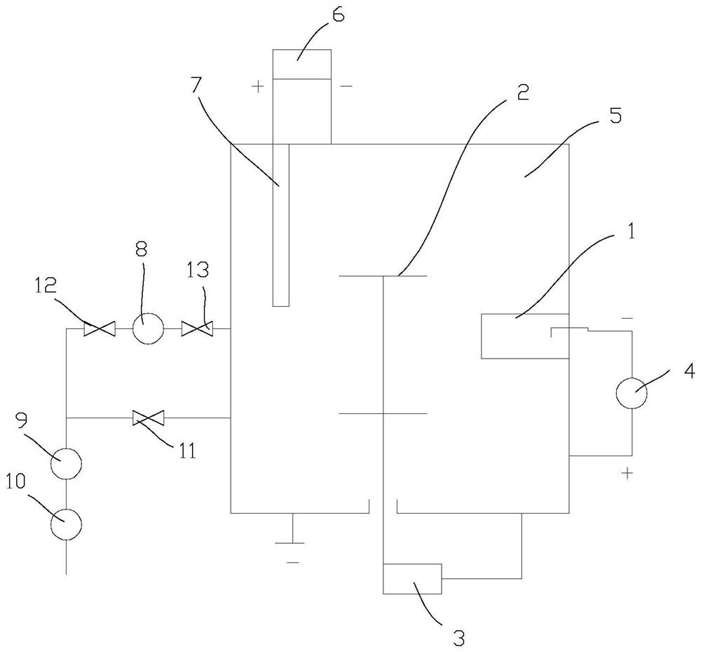
[0066] M2 high-speed steel surface activation process, using HC380 ion coating machine, using arc light electron source to assist surface activation, the principle is as follows figure 1 ,Specific steps are as follows

[0067] 1) Pre-treatment: Polish the HRC62-65 M2 high-speed steel sample after heat treatment, then ultrasonically clean it in alcohol for 10 minutes, dry it fully and put it into the vacuum chamber of the coating machine;

[0068] 2) Vacuuming: the background vacuum of the vacuum chamber is 5.0×10 -3 Pa;

[0069] 3) Heating to 500°C and keeping warm for 60 minutes;

[0070] 4) Enhanced cleaning of the arc electron source: Introduce argon gas, adjust the air pressure to 0.6Pa, turn on the arc electron source: turn on the main power supply of the arc electron source, adjust the cathode arc current to 60A; turn on the auxiliary anode, and adjust the current to 40A. Turn on the pulse bias power supply connected to the workpiece, adjust the negative bias voltage ...

Embodiment 2

[0077] 304 stainless steel ion surface activation, use HC1912 ion coating machine, use arc light electron source to assist surface activation, the specific steps are as follows

[0078] 1. Pre-treatment: After polishing the 304 steel sample, perform ultrasonic cleaning in alcohol for 10 minutes, fully dry and put it into the vacuum chamber of the coating machine;

[0079] 2. Vacuuming: the background vacuum of the vacuum chamber is 3.0×10 -3 Pa;

[0080] 3. Heat to 200°C and keep warm for 30 minutes;

[0081] 4. Arc light electron source enhances etching activation: argon gas is introduced, and the pressure is adjusted to 0.8Pa. Turn on the main power supply of the arc electron source, adjust the current of the cathode arc target to 60A, turn on the auxiliary anode power supply of the arc electron source, and adjust the auxiliary anode current to 40A. Turn on the pulse bias power supply, adjust the negative bias voltage to 300V, the duty cycle is 50%, and use the arc electr...


PUM


Abstract

A glow discharge surface activation process enhanced by an arc electron source for PVD coating: S1. Vacuumize; S2. Supply argon gas with a pressure of 0.1-1Pa, turn on the bias to generate argon glow discharge plasma activation etching; S3. Arc light electrons Source enhanced cleaning: S3‑1. Maintain the argon pressure at 0.1-1Pa, turn on the main power supply of the arc light electron source, ignite the cathode arc and discharge the arc, and the current is 20‑100A; turn on the arc light electron source auxiliary anode power supply, the current is 10-80A; adjust the bias Voltage 50-150V and duty cycle 20-80%, cleaning and activation for 1-2min; S3-2. The arc electron source remains unchanged, bias voltage 100V-200V, duty cycle 20-80%, enhanced ion cleaning and activation for 1-2min ;S3-3. Keep the arc electron source unchanged, adjust the bias voltage to 150-250V, duty cycle 20-80%, enhance ion cleaning for 1-2min; S3-4. Arc electron source unchanged, bias voltage 200-300V , the duty cycle is 20-80%, the enhanced ion cleaning is 1-2min; S3-5. The arc electron source remains unchanged, the bias voltage is 250-350V, the duty cycle is 20-80%, and the enhanced ion cleaning is 10-20min; S4. End . The invention has short etching activation time, low energy consumption, less gas consumption and can obtain excellent clean and smooth surface.

Description

technical field [0001] The invention relates to a PVD surface activation process, in particular to an arc electron source enhanced glow discharge surface activation process for PVD coating. [0002] technical background [0003] Traditional PVD technology usually uses gas glow discharge argon ion bombardment or arc metal ion bombardment to activate the surface of the workpiece before the coating layer of the workpiece in the furnace to improve the bonding force of the film base. [0004] A glow discharge is a gas discharge phenomenon in a low-pressure gas. In the traditional PVD coating technology, glow discharge is used as the surface activation of the substrate, that is, a small amount of argon gas is filled in the vacuumed furnace chamber, the anode of the bias power supply is connected to the furnace shell and grounded, and the cathode is connected to the hanging device. Workpiece on the workpiece rack. After the power is turned on, the thin argon gas generates a glow d...

Claims


Application Information

Patent Timeline
Patent Type & Authority Patents(China)
IPC IPC(8): C23C14/02C23C14/35C23C14/32
Inventor 李志荣李迎春刘江江
Owner DONGGUAN HUICHENG VACUUM TECH
Learn More