Positively-mounted integrated unit diode chip

An integrated unit and diode technology, applied in electrical components, electrical solid devices, circuits, etc., can solve the problems of LED light efficiency, heat dissipation and stability limitations, and achieve improved light extraction efficiency, large heat dissipation area, and high photoelectric conversion efficiency. Effect

Active Publication Date: 2019-06-21
SHENZHEN INST OF WIDE BANDGAP SEMICON
View PDF8 Cites 2 Cited by
  • Summary
  • Abstract
  • Description
  • Claims
  • Application Information

AI Technical Summary

Problems solved by technology

Therefore, LED light efficiency, heat dissipation and stability under high current will be severely limited

Method used


Image

  • Positively-mounted integrated unit diode chip
  • Positively-mounted integrated unit diode chip
  • Positively-mounted integrated unit diode chip

Examples


Embodiment 1

[0049] This embodiment provides a 6V high-voltage integrated unit light-emitting diode chip design, such as Figure 12-13 As shown, every two chip units are connected in series with each other to form a 6V high-voltage chip unit, and each 6V high-voltage chip unit is connected in parallel with each other. At this time, the ratio of series-parallel connection is 1:1. The units are connected in series with each other, and then connected in parallel with other N chip units. At this time, the ratio of series-parallel connection is 1:N. The circuit diagram is as follows Figure 12 shown.

[0050] Such as Figure 13 As shown, the 6V high-voltage chip units are insulated from each other, and the n-type gallium nitride (n-GaN) platform 7 is exposed for each unit, and the left chip is connected in series through the bridge metal in the middle. The n-electrode and the p-electrode of the chip on the right. The 6V chip units are connected in parallel with each other, so even if a certa...

Embodiment 2

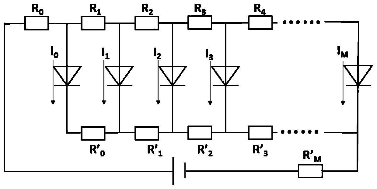
[0054] This embodiment provides a formal integration design method, image 3 It is a schematic circuit diagram of the unit diode chip series structure of the present invention.

[0055] where R 0 , R 1 , R 2 , R 3 , R 4 ... is the resistance from the P-type electrode electrode line between a plurality of unit diode chips to the quantum well active region; R' 0 ,R' 1 ,R' 2 ,R' 3 ,R' 4 …for multiple unit diode chips between

[0056]

[0057] The resistance of the N-type electrode electrode line to the active region of the quantum well. Usually in the Nth unit diode chip, R N =R NM +R Nc +R Np-GaN , where R NM is the electrode wire resistance of the P-type electrode, R Nc is the contact resistance of a p-type ohmic contact, R Np-GaN is the resistance of p-GaN material; similarly, in the Nth unit diode chip, R′ N =R' NM +R' Nc +R' Nn-GaN , where R'NM is the N-type electrode wire resistance, R' Nc is the contact resistance of n-type ohmic contact, R' Nn-Ga...

Embodiment 3

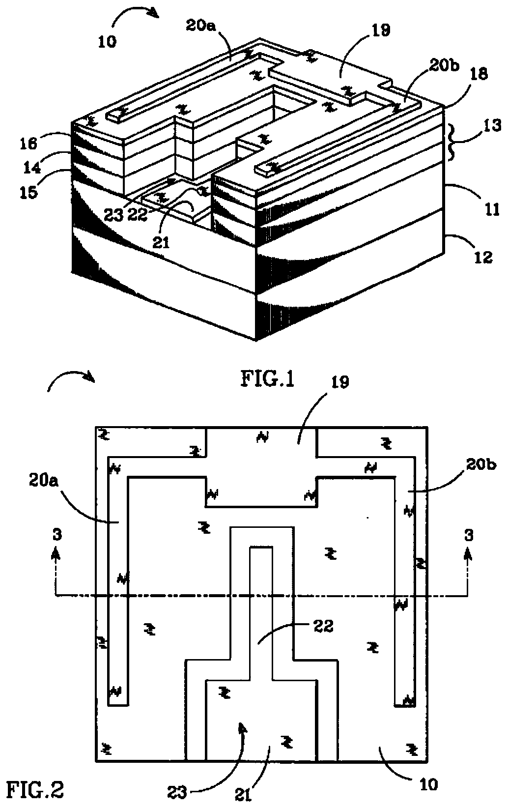
[0066] This embodiment provides a positively mounted integrated unit diode chip, the mesa structure area of ​​which is determined according to the current, such as Figure 5 to Figure 7 As shown, it includes N-type electrode 1 , P-type electrode 2 , ITO 3 , hole 11 , N-type electrode line 12 , and P-type electrode line 13 .

[0067] In the unit diode chip, the length of the diode unit row is fixed as L, and the diode units from the P-type electrode to the right are defined in sequence, and their widths are defined as L 0 , L 1 , L 2 , L 3 ,... L N …L M ; where the width of the diode unit satisfies L 0 >L 1 >L 2 >L 3 >…>L N ...> L M , the optimal design approximation is:

[0068]

[0069] According to L N And the area calculation formula to calculate the area of ​​the mesa structure.

[0070] In this embodiment, the front sectional view of the hole structure is added as Figure 5 As shown, the pore structure includes a plurality of pore units, the number of pore ...


PUM

PropertyMeasurementUnit
Diameteraaaaaaaaaa
Lengthaaaaaaaaaa
Widthaaaaaaaaaa

Abstract

This invention relates to the field of semiconductor materials and device processes, and in particular to semiconductor photoelectric devices. The invention provides a positively-mounted integrated unit diode chip, comprising a first conduction type electrode, a second conduction type electrode, and a diode mesa structure located between the first conduction type electrode and the second conduction type electrode, the diode mesa structure comprises n diode units, the n diode units are arranged in a geometric shape, and the width of the electrode width and the area of the mesa structure are determined according to the current. By adoption of the positively-mounted integrated unit diode chip provided by the invention, the technical problem that the diode structure has great limitation on three important parameters, that is, lumen efficiency, lumen density output and lumen cost in the prior art is solved, the lumen output of the unit diode chip in a unit area is improved, and the lumen cost is reduced.

Description

technical field [0001] The invention relates to the field of semiconductor materials and device technology, in particular to semiconductor optoelectronic devices. Background technique [0002] Conventional front-mounted integrated unit diode chips have uneven current diffusion, resulting in loss of luminous efficiency. The heat dissipation of the diode unit diode chip under the existing structure is realized through the sapphire substrate, and the heat dissipation is poor, thus affecting the efficiency and stability of the unit diode chip. Therefore, the main application field of front-mounted light-emitting diode unit diode chips is the small and medium power unit diode chip market below 0.5 watts, and it is impossible to provide products with high lumen output per unit area. Uneven current diffusion, uneven thermal diffusion, and uneven light extraction lead to great limitations in three important parameters: lumen efficiency, lumen density output, and lumen cost. Currentl...

Claims


Application Information

Patent Timeline
IPC IPC(8): H01L25/075H01L33/06H01L33/32H01L33/62
CPCH01L25/0753H01L33/06H01L33/325H01L33/62
Inventor 蒋振宇闫春辉
Owner SHENZHEN INST OF WIDE BANDGAP SEMICON
Why Eureka
Try Eureka