
System used for processing sludge

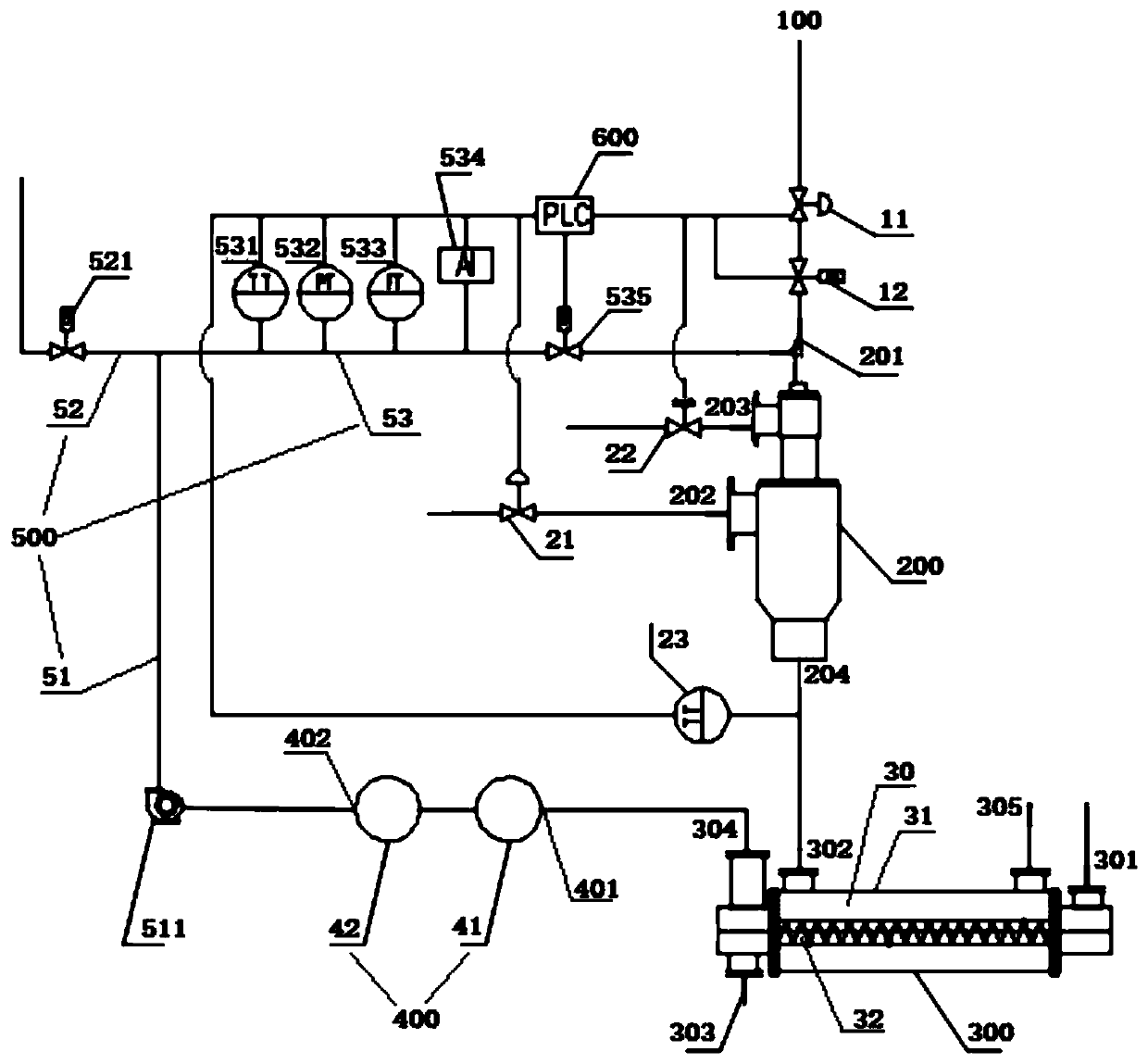
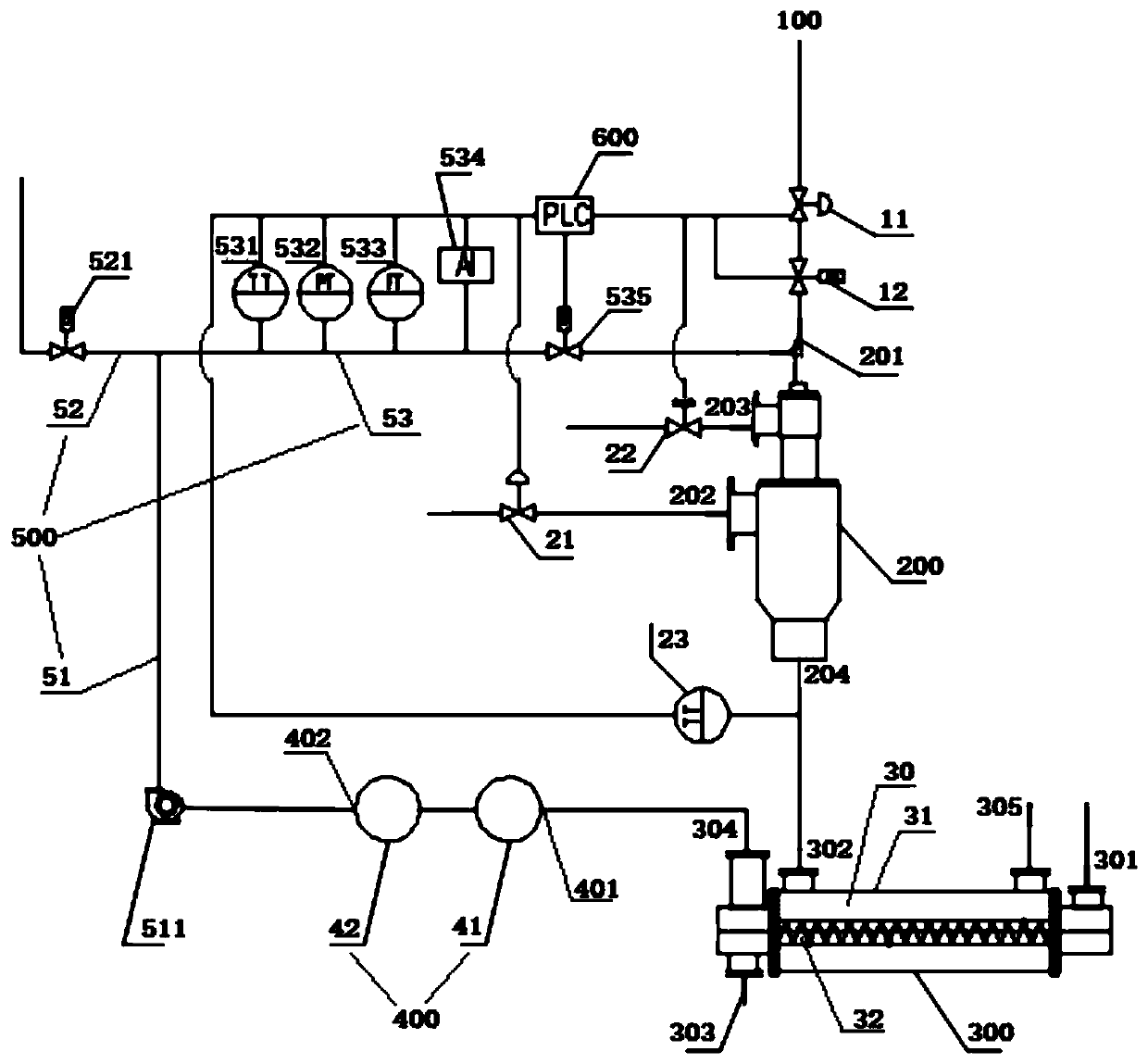
A sludge and inlet technology is applied in the field of sludge resource utilization process, which can solve the problems of insufficient combustion of combustible gas, environmental pollution by nitrogen oxides, and unstable pyrolysis gas composition and rate.

Pending Publication Date: 2019-07-02
北京云水浩瑞环境科技有限公司
View PDF10 Cites 1 Cited by
  • Summary
  • Abstract
  • Description
  • Claims
  • Application Information

AI Technical Summary

Problems solved by technology

[0003] Before the pyrolysis gas is produced, the fuel of the burner is municipal natural gas. At this time, the gas supply pressure of the municipal gas is basically unchanged, and the calorific value is stable, which is basically stable for the combustion of the burner; with the sludge carbonization and pyrolysis The pyrolysis gas is gradually produced, and the pyrolysis gas will enter the burner of the carbonization machine to participate in the combustion. The composition and rate of the generated pyrolysis gas are not fixed, which has a great impact on the combustion of the burner: 1. When the heat When the output of pyrolysis gas is low, it is easy to cause the burner to extinguish the fire; 2. When the output of pyrolysis gas is high, it will lead to insufficient combustion of combustible gas in the burner, producing a large amount of nitrogen oxides to pollute the environment, and at the same time, carbon oxides are produced, resulting in explosions

Method used


Image

  • System used for processing sludge
  • System used for processing sludge

Examples


Embodiment Construction

[0024] Embodiments of the present invention are described in detail below, examples of which are shown in the drawings, wherein the same or similar reference numerals designate the same or similar elements or elements having the same or similar functions throughout. The embodiments described below by referring to the figures are exemplary and are intended to explain the present invention and should not be construed as limiting the present invention.

[0025] In describing the present invention, it should be understood that the terms "center", "longitudinal", "transverse", "length", "width", "thickness", "upper", "lower", "front", " Back", "Left", "Right", "Vertical", "Horizontal", "Top", "Bottom", "Inner", "Outer", "Clockwise", "Counterclockwise", "Axial" , "radial", "circumferential" and other indicated orientations or positional relationships are based on the orientations or positional relationships shown in the drawings, which are only for the convenience of describing the ...


PUM


Abstract

The invention discloses a system used for processing sludge. The system comprises a municipal combustion gas conveying pipeline, a combustor, a destructive distillation machine, a purifying device, apyrolysis gas conveying pipeline, and a control device; the municipal combustion gas conveying pipeline is provided with a municipal combustion gas regulating valve, and a rapid switching valve; the combustor is provided with a secondary wind inlet, an oxidant gas inlet, and a combustion flue gas outlet, the secondary wind inlet is provided with a secondary wind regulating valve, the oxidant gas inlet is provided with an oxidant gas regulating valve, and the combustion flue gas outlet is provided with a flue gas temperature sensor; the destructive distillation machine is provided with a sludgeinlet, a combustion flue gas inlet, a pyrolytic carbon outlet, and a pyrolytic gas outlet; the purifying device is provided with a pyrolytic gas inlet and a purified gas outlet; the pyrolysis gas conveying pipeline comprises a first branch pipeline and a second branch pipeline, the first branch pipeline is provided with a blowoff valve, the second branch pipeline is provided with a pyrolysis gastemperature sensor, a pyrolysis gas pressure sensor, a pyrolysis gas flow amount sensor, a pyrolysis gas analyzer, and a pyrolysis gas regulating valve; the control device is connected with the municipal combustion gas regulating valve, the rapid switching valve, the secondary wind regulating valve, the oxidant gas regulating valve, the flue gas temperature sensor, the blowoff valve, the pyrolysisgas temperature sensor, the pyrolysis gas pressure sensor, the pyrolysis gas flow amount sensor, the pyrolysis gas analyzer, and the pyrolysis gas regulating valve.

Description

technical field [0001] The invention belongs to sludge resource utilization technology, in particular to a system for treating sludge. Background technique [0002] The sludge drying pyrolysis carbonization treatment process is a relatively advanced sludge treatment technology, which can eliminate the dioxin pollution produced by sludge incineration, and at the same time meet the needs of the country's greenhouse gas emission reduction. The biochar produced is mainly used for building materials and gardens Soil improvement, etc., the specific process is: the sludge (moisture content 80-90%) produced by sewage treatment is treated by a dryer three times to reduce the moisture content of the sludge to below 20%, and the moisture content of the sludge is reduced to 20% by a screw conveyor. % of the sludge is transported to the inside of the retort, and by heating the outside of the retort, the sludge in the retort is heated to 660-780°C by heat conduction, so that the component...

Claims


Application Information

Patent Timeline
Patent Type & Authority Applications(China)
IPC IPC(8): C02F11/10C10B53/00
CPCC02F11/10C10B53/00Y02W10/40
Inventor 王超兰玉顺刘维娜代锁柱武振恒李东亮陈海洋雷小雪代江燕
Owner 北京云水浩瑞环境科技有限公司
Learn More