
Piezoelectric and electromagnetic coupling vibration sensor

A vibration sensor, electromagnetic coupling technology, applied in piezoelectric effect/electrostrictive or magnetostrictive motors, generators/motors, electrical components, etc., can solve problems such as poor DC response, achieve small signal distortion, voltage Frequency bandwidth, improve the effect of poor DC response

Pending Publication Date: 2019-07-09
XIAN TECH UNIV
View PDF0 Cites 4 Cited by
  • Summary
  • Abstract
  • Description
  • Claims
  • Application Information

AI Technical Summary

Problems solved by technology

The disadvantage is that some piezoelectric materials need moisture-proof treatment, and the output DC response is poor. It is necessary to use a high input impedance circuit or a charge amplifier to overcome this defect.

Method used


Image

  • Piezoelectric and electromagnetic coupling vibration sensor
  • Piezoelectric and electromagnetic coupling vibration sensor
  • Piezoelectric and electromagnetic coupling vibration sensor

Examples


Embodiment Construction

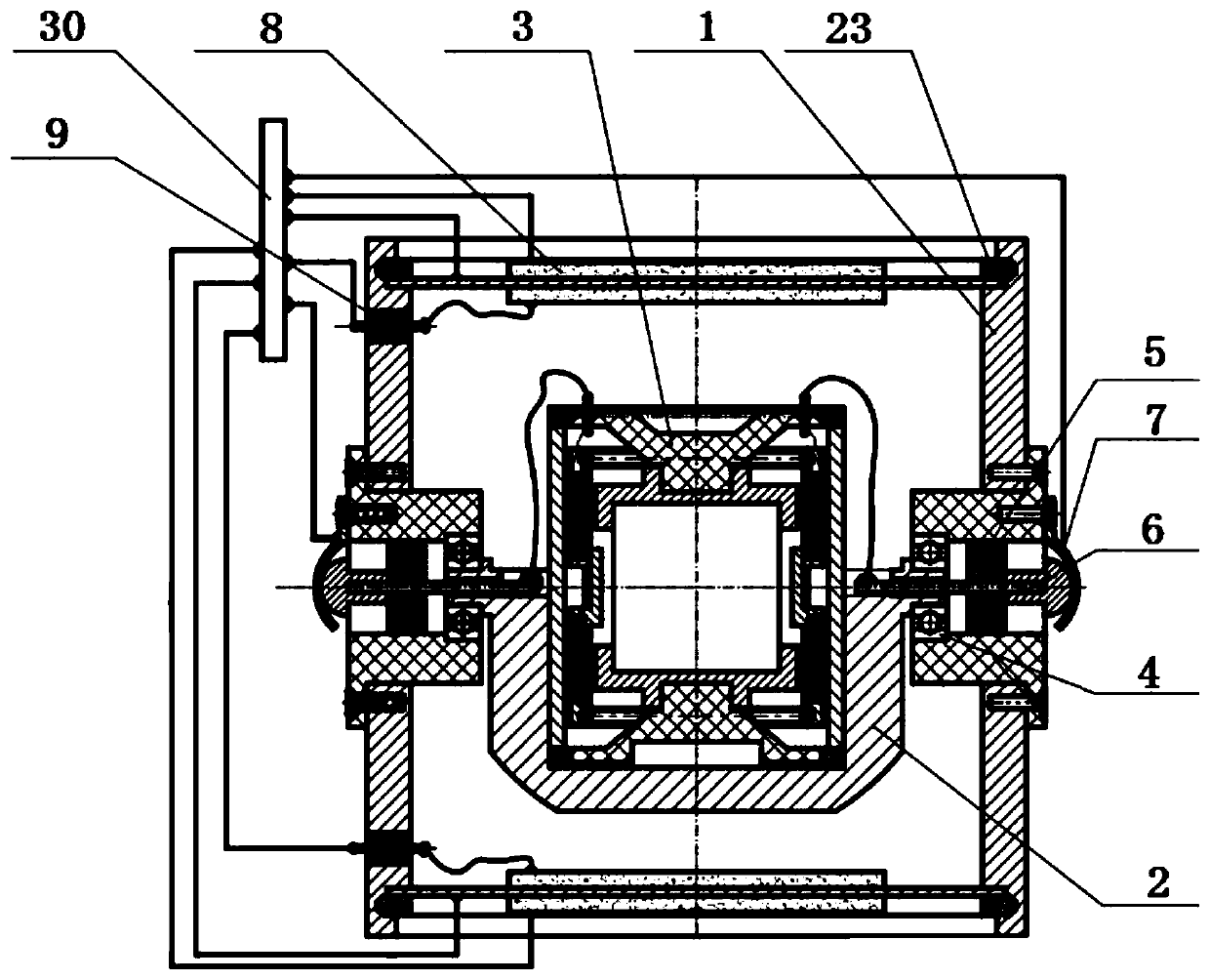
[0028] The present invention will be further described in detail below through specific embodiments in conjunction with the accompanying drawings. Wherein, similar elements in different implementations adopt associated similar element numbers. In the following implementation manners, many details are described for better understanding of the present application. However, those skilled in the art can readily recognize that some of the features can be omitted in different situations, or can be replaced by other elements, materials, and methods. In some cases, some operations related to the application are not shown or described in the description, this is to avoid the core part of the application being overwhelmed by too many descriptions, and for those skilled in the art, it is necessary to describe these operations in detail Relevant operations are not necessary, and they can fully understand the relevant operations according to the description in the specification and genera...


PUM


Abstract

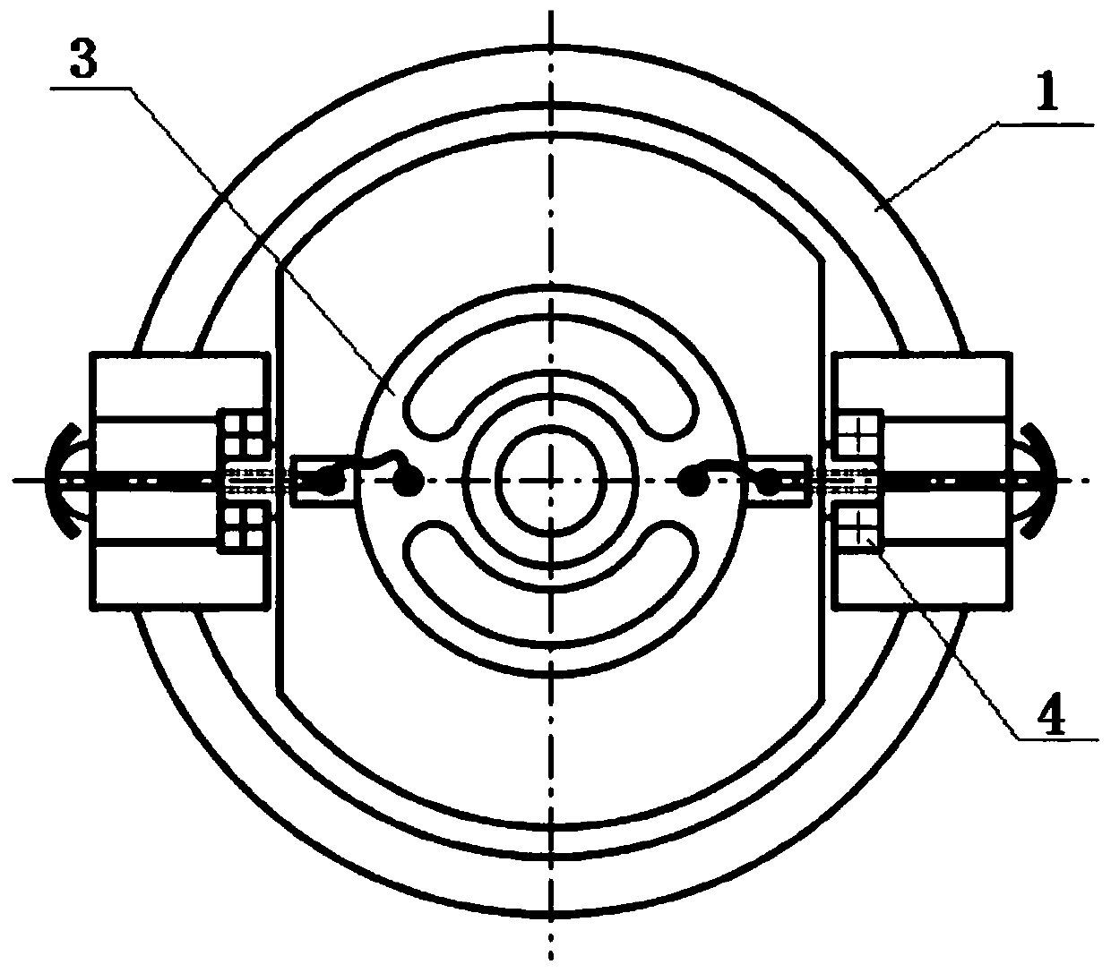
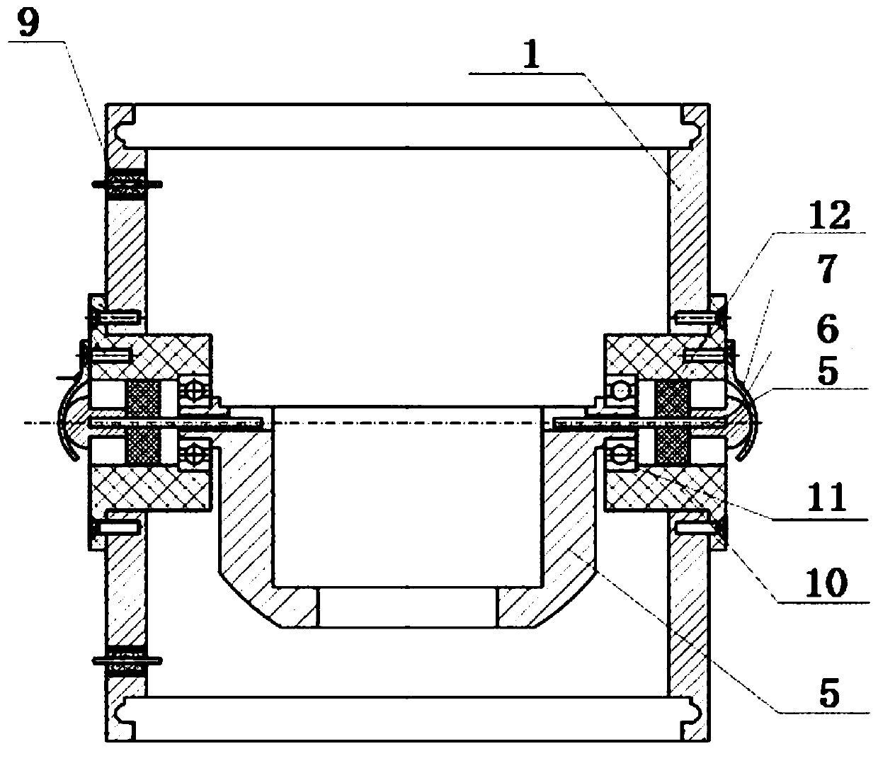
The invention relates to a piezoelectric and electromagnetic coupling vibration sensor, which comprises a cylinder body. The inside of the cylinder body constitutes a sealed resonant cavity. An electromagnetic vibration system and a piezoelectric vibration system are arranged in the cylinder body. The external vibration causes the electromagnetic vibration system to vibrate and generate electromagnetic electrical signals. When the electromagnetic vibration system vibrates, the airflow in the resonant cavity fluctuates, and the piezoelectric vibration system vibrates and generates piezoelectricelectrical signals. Thus, the coupling between electromagnetic electrical signals and piezoelectric electrical signals is realized. An electromagnetic vibration sensor and a piezoelectric vibrator are installed in the sealed resonant cavity in the cylinder body. The spring-mass vibration system of the electromagnetic vibration sensor vibrates under external vibration to cause the airflow fluctuation in the cavity, and the airflow fluctuation drives the piezoelectric vibrator to vibrate and generate piezoelectric electrical signals. The two effects are in the same frequency, so that the frequency difference between signals is avoided, and the post-processing of signals is facilitated.

Description

technical field [0001] The invention relates to a vibration sensor, in particular to a piezoelectric and electromagnetic coupling vibration sensor. The invention can be used for various vibration detection, such as geological exploration, equipment vibration, earthquake monitoring and the like in various geological conditions. It is especially suitable for vibration monitoring in the field of underwater acoustics and seismic exploration in environments such as oceans, lakes, and swamps. Background technique [0002] The electromagnetic vibration sensor is an electromechanical conversion device that converts vibration energy into electrical energy. The coil is suspended in the gap magnetic field formed by the permanent magnet, and the vibration causes relative motion between the coil and the magnet. The coil cuts the magnetic field line to generate an induced electromotive force in the coil, and the output forms an electrical signal. The coil frame is suspended by a spring ...

Claims


Application Information

Patent Timeline
Patent Type & Authority Applications(China)
IPC IPC(8): H02K35/02H02N2/18
CPCH02K35/02H02N2/186
Inventor 穆静王长元
Owner XIAN TECH UNIV
Learn More