Photoacoustic signal detection and imaging method based on micro-nano motor

A micro-nano motor, photoacoustic signal technology, applied in measurement devices, diagnostic recording/measurement, material analysis by optical means, etc., can solve the problems of low motor driving speed and complex preparation process, and achieve breakthroughs in technical bottlenecks and simplification. The effect of the drive guide mechanism

Active Publication Date: 2019-07-12
HARBIN INST OF TECH
View PDF8 Cites 5 Cited by
  • Summary
  • Abstract
  • Description
  • Claims
  • Application Information

AI Technical Summary

Problems solved by technology

On the whole, the first two micro-nano motors are mainly prepared by means of electrodeposition or micro-nano processing, and the preparation process is relatively complicated. Later, many researchers have developed a new micro-nano motor preparation method based on a method similar to rotational motion. surface action driven
But the resulting motor drive speed is lower

Method used


Image

  • Photoacoustic signal detection and imaging method based on micro-nano motor
  • Photoacoustic signal detection and imaging method based on micro-nano motor
  • Photoacoustic signal detection and imaging method based on micro-nano motor

Examples


specific Embodiment approach 1

[0030] Such as Figure 1-4 As shown, the micro-nano motor-based photoacoustic signal detection and imaging method, the micro-nano motor-based photoacoustic signal detection and imaging method includes:

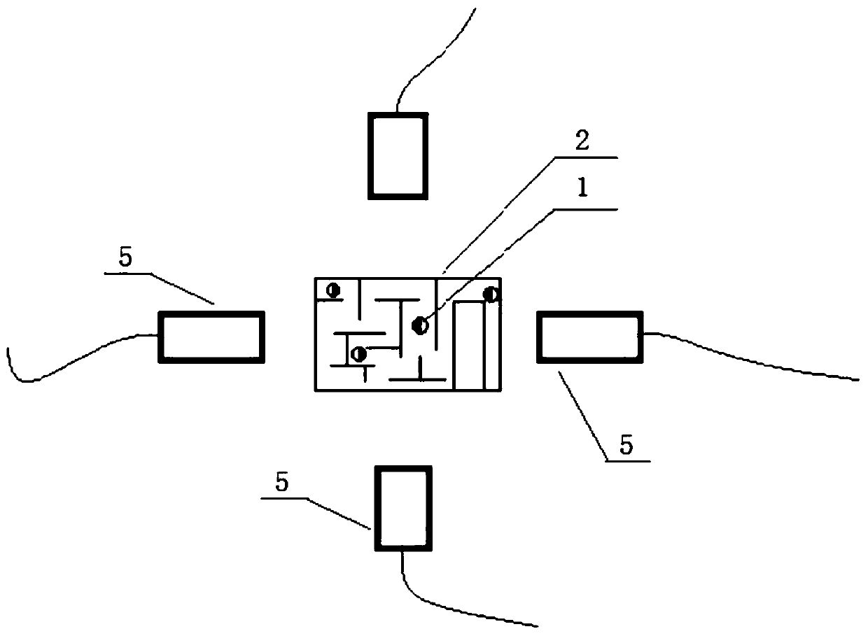
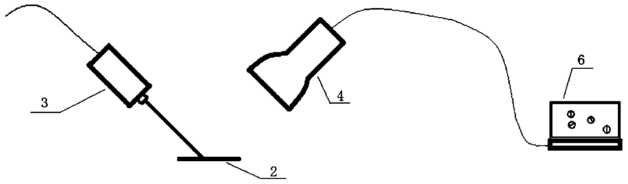
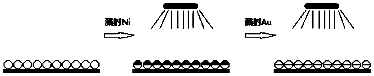
[0031] S1: A detection and imaging system to be used for photoacoustic signal detection and imaging based on micro-nano motors. The system includes sputtering ferromagnetic metal layer 1-1 and photothermal conversion metal layer 1-2 sequentially on one hemispherical surface Micro-nano motor 1 composed of base spheres 1-3, container containing deionized water 2, nanosecond pulse near-infrared laser light source 3, ultrasonic detector 4, power amplifier, filter, electromagnetic coil 5, and images equipped with imaging algorithm software The computer 6 is reconstructed; the micro-nano motor 1 is located in the container 2; the output end of the ultrasonic detector 4 is electrically connected to the input end of the power amplifier; the output end of the power amplifier is electri...

specific Embodiment approach 2

[0037] Such as Figure 1-4 As shown, the container 2 is one of a clean Petri dish, a capillary or a microchannel on a PDMS substrate.

specific Embodiment approach 3

[0039] Such as Figure 1-4 As shown, the wavelength range of the nanosecond pulsed near-infrared laser light source 3 is 780nm-808nm, and the pulse width is 10-15 nanoseconds.


PUM

PropertyMeasurementUnit
Wavelengthaaaaaaaaaa
Magnetic field strengthaaaaaaaaaa
Sizeaaaaaaaaaa

Abstract

The invention relates to the field of micro-nano motor application, and particularly relates to a photoacoustic signal detection and imaging method based on a micro-nano motor, which comprises the following steps: S1, preparing a photoacoustic signal detection and imaging system based on the micro-nano motor for detection and imaging; S2, generating a magnetic field by an electromagnetic coil to drive and guide the micro-nano motor; S3, irradiating the micro-nano motor through a nanosecond pulse near-infrared laser light source, exciting thermoelastic expansion of surrounding liquid based on the plasmon effect of a photothermal conversion metal layer, periodically irradiating the micro-nano motor to generate photothermal conversion, and generating an ultrasonic photoacoustic signal; S4, after detecting the ultrasonic photoacoustic signal by the ultrasonic detector, amplifying and filtering the ultrasonic photoacoustic signal, and transmitting the signal to a started image reconstruction computer for algorithm imaging. The method can achieve the tracking, positioning and imaging of the micro-nano motor in the organism, and breaks through the technical bottleneck that the micro-nanomotor is difficult in tracking and imaging in the organism.

Description

technical field [0001] The invention relates to the application field of micro-nano motors, in particular to a photoacoustic signal detection and imaging method based on micro-nano motors. Background technique [0002] In 2004, the first complete chemically catalyzed micro-nano motor was born—Au / Pt bimetallic nanowires, which consume hydrogen peroxide fuel through Pt catalysis to drive the motor. In the following ten years, people have gained a deeper understanding of the driving methods of micro-nano motors, not only in chemically driven micro-nano motors, but also in external field drives, such as external magnetic fields, electric fields, ultrasonic fields, and light. Lots of new motors. These external field-driven motors are extremely important for the application of micro-nanomotors in vivo, because they do not require chemical fuels like chemically driven micro-nanomotors, so they can be applied to drug delivery, biosensing and micro-repair in vivo. [0003] The magn...

Claims


Application Information

Patent Timeline
IPC IPC(8): A61B5/00G01N21/17G01N29/06
CPCA61B5/0095G01N21/1702G01N29/0654
Inventor 李隆球周德开岳红尔李天龙常晓丛
Owner HARBIN INST OF TECH
Why Eureka
Try Eureka