

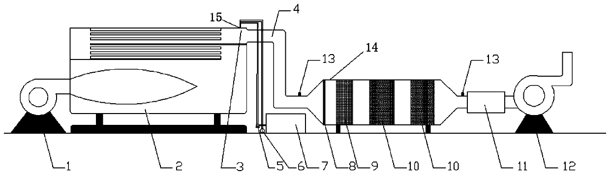
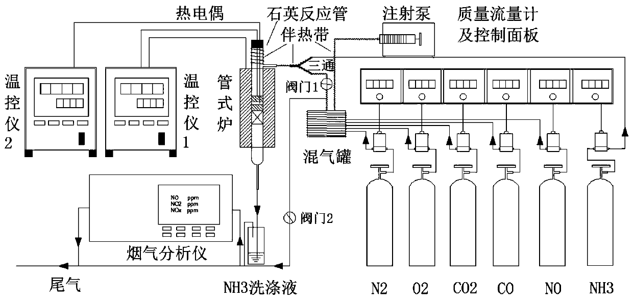
Integrated purification method and device for CO and NOx removal of gas boiler
A gas-fired boiler and purification device technology, applied in chemical instruments and methods, gas treatment, separation methods, etc., can solve problems such as energy waste, achieve the effects of improving the emission compliance rate, reducing the number of devices, and being easy to control
- Summary
- Abstract
- Description
- Claims
- Application Information
AI Technical Summary
Problems solved by technology
Method used
Image

Examples
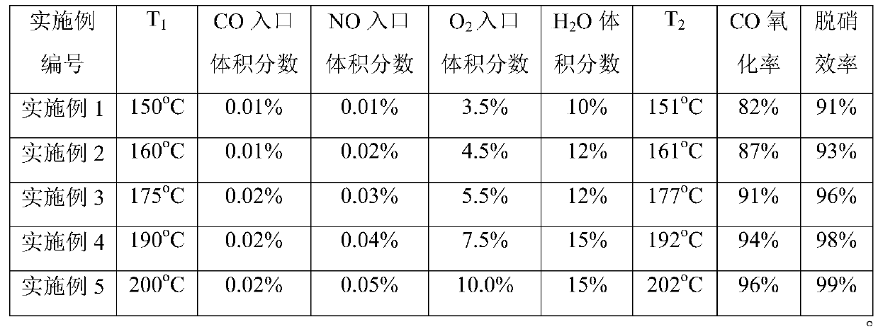
Embodiment 1
[0034] Experimental conditions: set temperature T 1 150°C, reaction gas components NO volume fraction 0.01%, NH 3 Volume fraction 0.01%, CO volume fraction 0.01%, CO 2 Volume fraction 2.0%, O 2 Volume fraction 3.5%, H 2 O volume fraction 10%, N 2 For balance. At this time, the temperature T of the gap between the CO oxidant and the denitration catalyst 2 The temperature is 151°C, the CO oxidation rate is 82%, and the denitrification efficiency is 91%.
Embodiment 2
[0036] Experimental conditions: set temperature T 1 160°C, reaction gas components NO volume fraction 0.02%, NH 3 Volume fraction 0.02%, CO volume fraction 0.01%, CO 2 Volume fraction 3.0%, O 2 Volume fraction 4.5%, H 2 O volume fraction 12%, N 2 For balance. At this time, the temperature T of the gap between the CO oxidant and the denitration catalyst 2 The temperature is 161°C, the CO oxidation rate is 87%, and the denitrification efficiency is 93%.
Embodiment 3
[0038] Experimental conditions: set temperature T 1 at 175°C, the reaction gas component NO volume fraction is 0.03%, NH 3 Volume fraction 0.03%, CO volume fraction 0.02%, CO 2 Volume fraction 4.0%, O 2 Volume fraction 5.5%, H 2 O volume fraction 12%, N 2 For balance. At this time, the temperature T of the gap between the CO oxidant and the denitration catalyst 2 The temperature is 177°C, the CO oxidation rate is 91%, and the denitrification efficiency is 96%.
PUM
 Abstract
Description
Claims
Application Information