Tool setting method aiming at processing terahertz slow wave structural member
A slow-wave structure, terahertz technology, used in metal processing machinery parts, metal processing, metal processing equipment and other directions, can solve the problems of clamping error, low processing efficiency, etc., to reduce changing parameters, improve mirror fit, The effect of reducing tool setting errors
- Summary
- Abstract
- Description
- Claims
- Application Information
AI Technical Summary
Problems solved by technology
Method used
Image
Examples
specific Embodiment approach 1
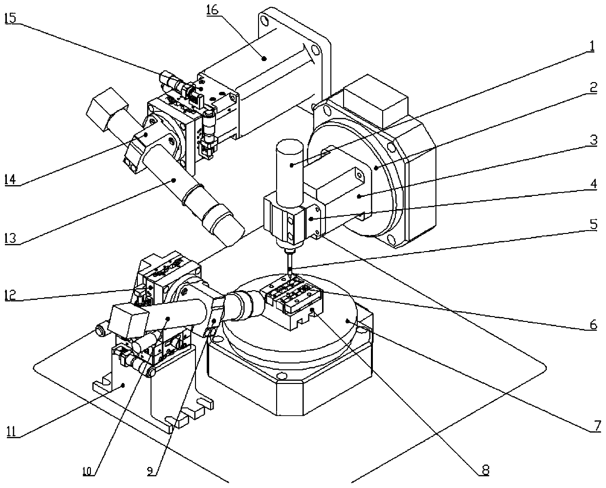
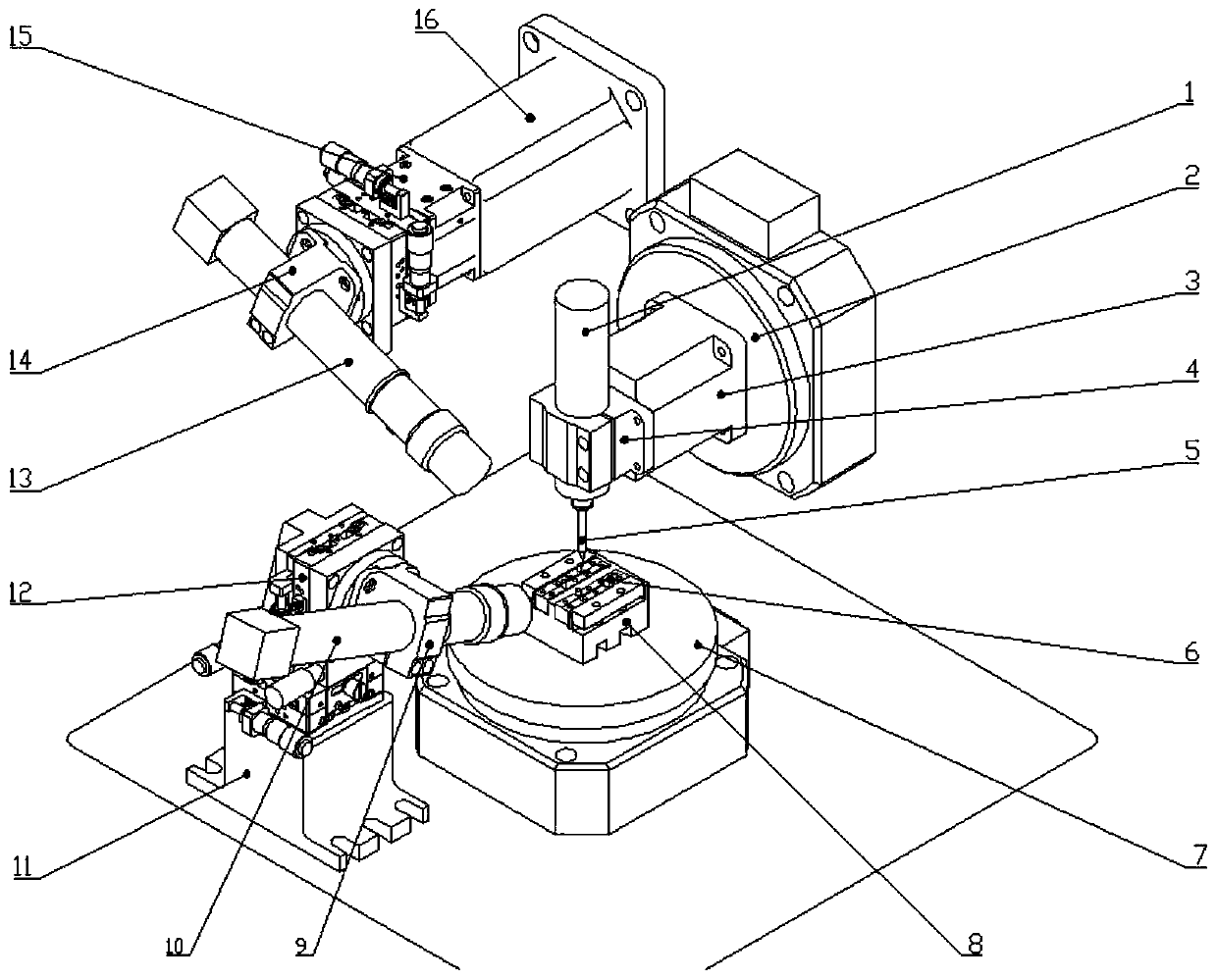
[0041] Specific implementation mode one: as figure 1 As shown, the steps of the tool setting method for processing terahertz slow wave structural parts in this embodiment are as follows:
[0042] Step 1. Establishment and calibration of the coordinate system:
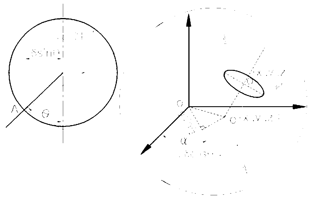
[0043](1) According to the Lagrangian method, take the main body of the machine tool as the benchmark, and establish an absolute coordinate system (X, Y, Z) at the intersection of the horizontal worktable and the A-axis rotation axis as the origin;
[0044] (2) With the plane where the horizontal CCD camera 10 is located as the YOZ plane, the plane where the suspended CCD camera 13 is located is the XOZ plane, and a Cartesian coordinate system is established, and the position of the horizontal CCD camera 10 and the suspended CCD camera 13 clamping points, the position of the fixture Carry out three-dimensional calibration, and then clamp the workpiece 6, define the tool setting control body determined according to the ...
specific Embodiment approach 2
[0051] Specific implementation mode two: as figure 1 As shown, the terahertz slow wave structure processing tool setting device adopted by the tool setting method in this embodiment includes an electric spindle 1, a C-axis rotary table 2, an electric spindle support frame 3, an electric spindle chuck 4, and a hard micro milling cutter 5. Work piece 6, A-axis rotary table 7, chuck body 8, horizontal CCD chuck 9, horizontal CCD camera 10, horizontal CCD camera positioning block 11, horizontal CCD camera fine-tuning module 12, suspension CCD camera 13, suspension CCD camera Chuck 14, suspended CCD camera fine-tuning module 15 and suspended CCD camera positioning block 16; The horizontal CCD camera is connected with the horizontal CCD camera fine-tuning module 12 through the horizontal CCD chuck 9, and the suspended CCD camera is connected with the suspended CCD camera through the suspended CCD camera chuck 14 The fine-tuning module 15 is connected, the horizontal CCD camera fine-...
specific Embodiment approach 3
[0052] Specific implementation mode three: as figure 1 As shown, the horizontal CCD camera 10 of this embodiment is a 10-million-pixel variable magnification camera. Such a design can realize accurate tool setting in the ultra-precision micro-milling process of the folded waveguide slow-wave structural parts in the low-frequency terahertz band, and the error is controlled within the range of 0.3um. Other compositions and connections are the same as those in Embodiment 1 or 2.
PUM
 Abstract
Description
Claims
Application Information
 - R&D
- Intellectual Property
- Life Sciences
- Materials
- Tech Scout
- Unparalleled Data Quality
- Higher Quality Content
- 60% Fewer Hallucinations
Browse by: Latest US Patents, China's latest patents, Technical Efficacy Thesaurus, Application Domain, Technology Topic, Popular Technical Reports.
© 2025 PatSnap. All rights reserved.Legal|Privacy policy|Modern Slavery Act Transparency Statement|Sitemap|About US| Contact US: help@patsnap.com


