

Orthopedic robot
A robotic and orthopedic technology, applied in the field of robotics, can solve problems such as manual dumping, and achieve the effects of ensuring life safety, reducing the chance of infection, and saving ground space
- Summary
- Abstract
- Description
- Claims
- Application Information
AI Technical Summary
Problems solved by technology
Method used
Image

Examples
Embodiment 1
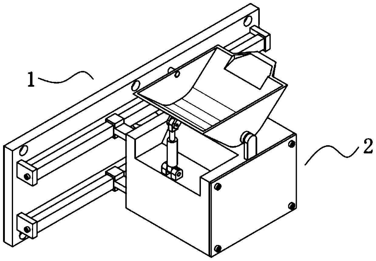
[0055] An orthopedic robot such as Figure 1-2 As shown in and 7, it includes a running part 1, a transfer part 2 and a driving part 3, the running part 1 and the transfer part 2 are slidingly connected, the driving part 3 and the running part 1 are transmission connected, and the driving The part 3 is fixedly connected with the transfer part 2;
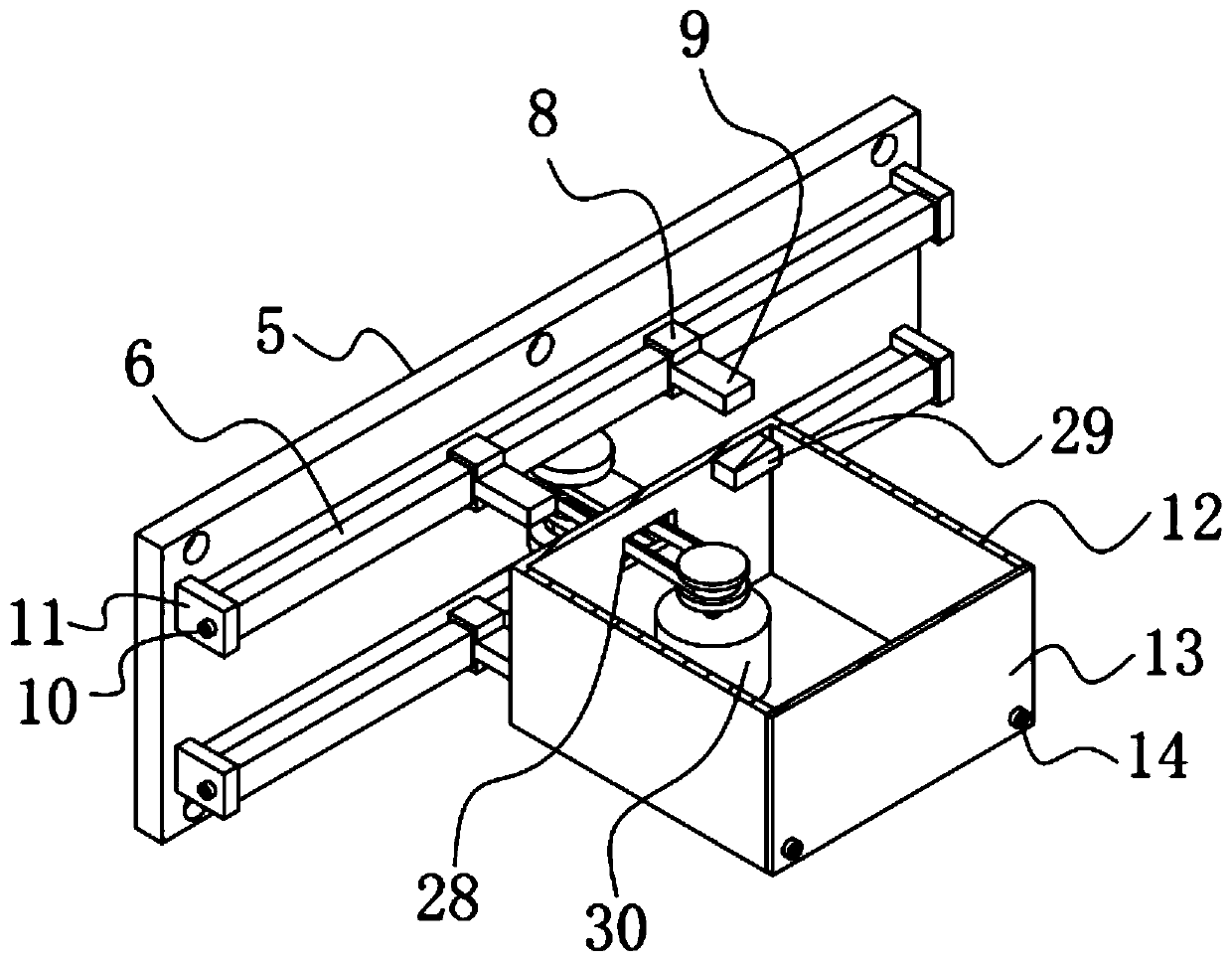
[0056] Such as figure 1 and 2 As shown, the running part 1 includes a mounting plate 5, two slide rails 6, four sliders 8 and four connecting rods 9, and the two slide rails 6 are symmetrically fixed on one side of the mounting plate 5 Above, the four sliders 8 are symmetrically clamped and slidably installed on the two slide rails 6, and the four sliders 8 are respectively fixedly connected to the four connecting rods 9;
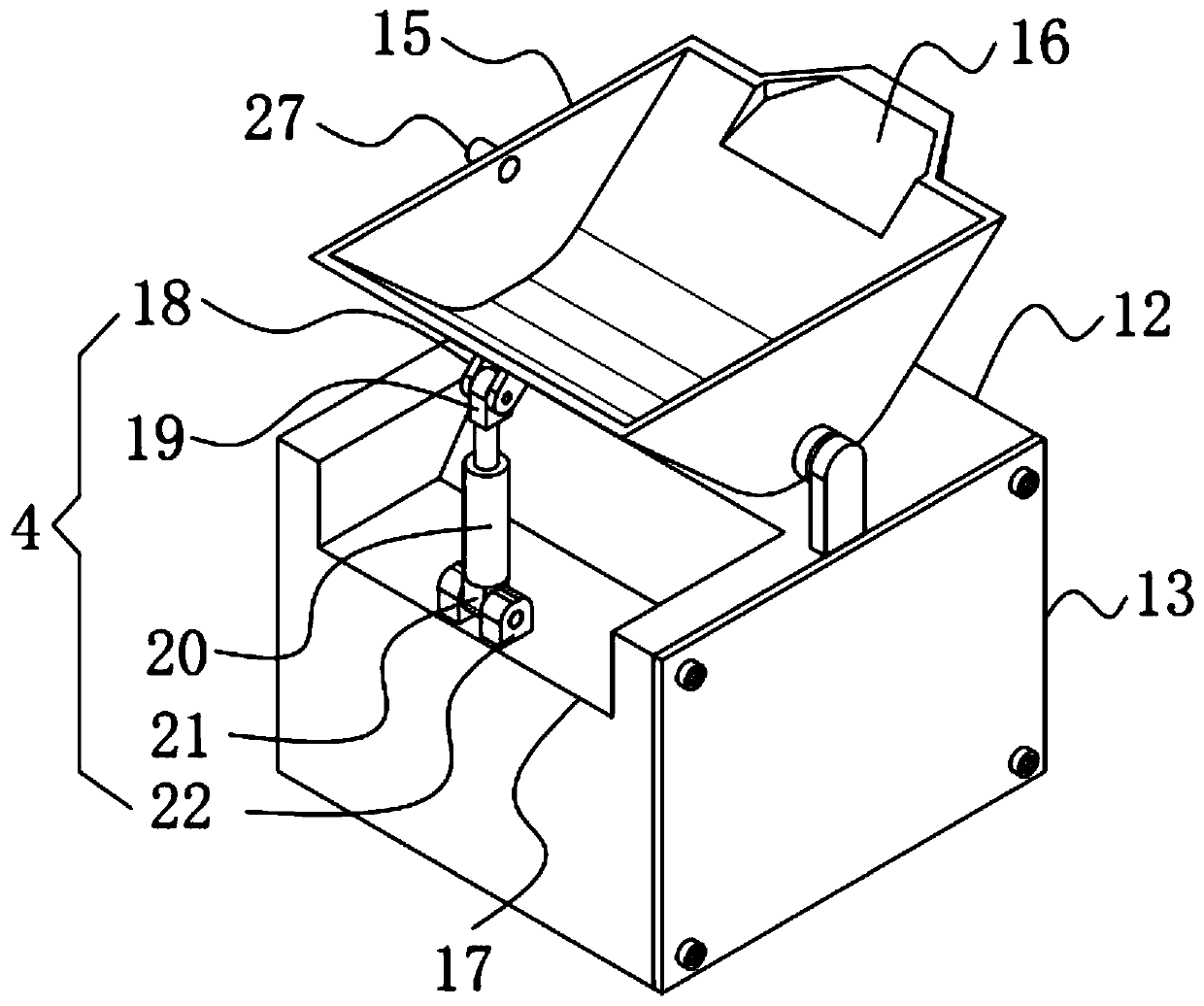
[0057] Such as figure 1 , 2 , 3 and 5, the transfer unit 2 includes a square housing 12, a storage bucket 15, a lifting device 4, two circular collars 23, two round shafts 24 and two support seats 25, the squ...
Embodiment 2
[0080] The difference from Example 1 is that the surface of the storage bucket 15 is also provided with a protective layer, and the protective layer is prepared by the following method:
[0081] Take the following raw materials and weigh them by weight: 25 parts of polytetrafluoroethylene, 12 parts of calcium carbonate powder, 12 parts of nano-silver powder, 10 parts of melamine resin, 8 parts of ceramic powder, 9 parts of titanium dioxide powder, 3 parts of alcohol ester twelve, three 3 parts of ethanolamine, 2 parts of emulsified silicone oil and 30 parts of water;
[0082] S1. Add the weighed alcohol ester dodecane, triethanolamine, emulsified silicone oil and water into the mixer and stir for 16min at a stirring speed of 550r / min to prepare a mixed solution;
[0083] S2, adding polytetrafluoroethylene, calcium carbonate powder, nano-silver powder, melamine resin, ceramic powder and titanium dioxide powder into a pulverizer for pulverization until the particle diameter of t...
Embodiment 3
[0089] The difference with embodiment 2 is the preparation of protective layer, and its specific preparation method is as follows:
[0090] Take the following raw materials and weigh them by weight: 30 parts of polytetrafluoroethylene, 14 parts of calcium carbonate powder, 14 parts of nano-silver powder, 13 parts of melamine resin, 9 parts of ceramic powder, 10 parts of titanium dioxide powder, 4 parts of alcohol ester twelve, three 4 parts of ethanolamine, 3 parts of emulsified silicone oil and 40 parts of water;
[0091] S1. Add the weighed alcohol ester dodecane, triethanolamine, emulsified silicone oil and water into the mixer and stir for 19min at a stirring speed of 600r / min to prepare a mixed solution;
[0092] S2, adding polytetrafluoroethylene, calcium carbonate powder, nano-silver powder, melamine resin, ceramic powder and titanium dioxide powder into a pulverizer for pulverization until the particle diameter of the material is not greater than 100nm to obtain a mixe...
PUM
 Abstract
Description
Claims
Application Information