Phase change-based flue gas end dehydration fine dust removal device

A technology for fine dust removal and flue gas, which is applied in the field of air pollution control, can solve the problems of water consumption, low heat exchange efficiency, heavy absorption tower weight, etc. Effect

Pending Publication Date: 2019-08-06
ANHUI UNIVERSITY OF TECHNOLOGY
View PDF2 Cites 3 Cited by
  • Summary
  • Abstract
  • Description
  • Claims
  • Application Information

AI Technical Summary

Problems solved by technology

However, the above dust and mist removal devices also have relatively large deficiencies. Among them, the heat exchange medium of the tube-grid heat exchanger uses circulating water, which consumes water resources, and has low heat exchange efficiency, large volume, and heavy weight of the absorption tower; Heaters and demisters are arranged in sequence and flushing nozzles are distributed. The equipment layout is relatively complicated, maintenance is difficult, and it is difficult to achieve fine dust removal

Method used


Image

  • Phase change-based flue gas end dehydration fine dust removal device
  • Phase change-based flue gas end dehydration fine dust removal device
  • Phase change-based flue gas end dehydration fine dust removal device

Examples


Embodiment 1

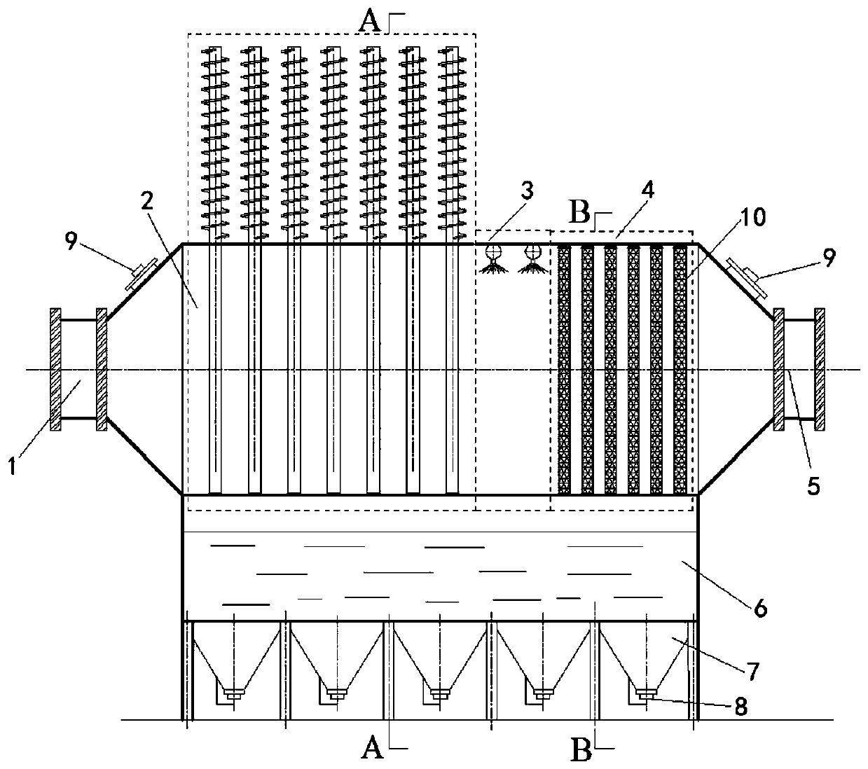
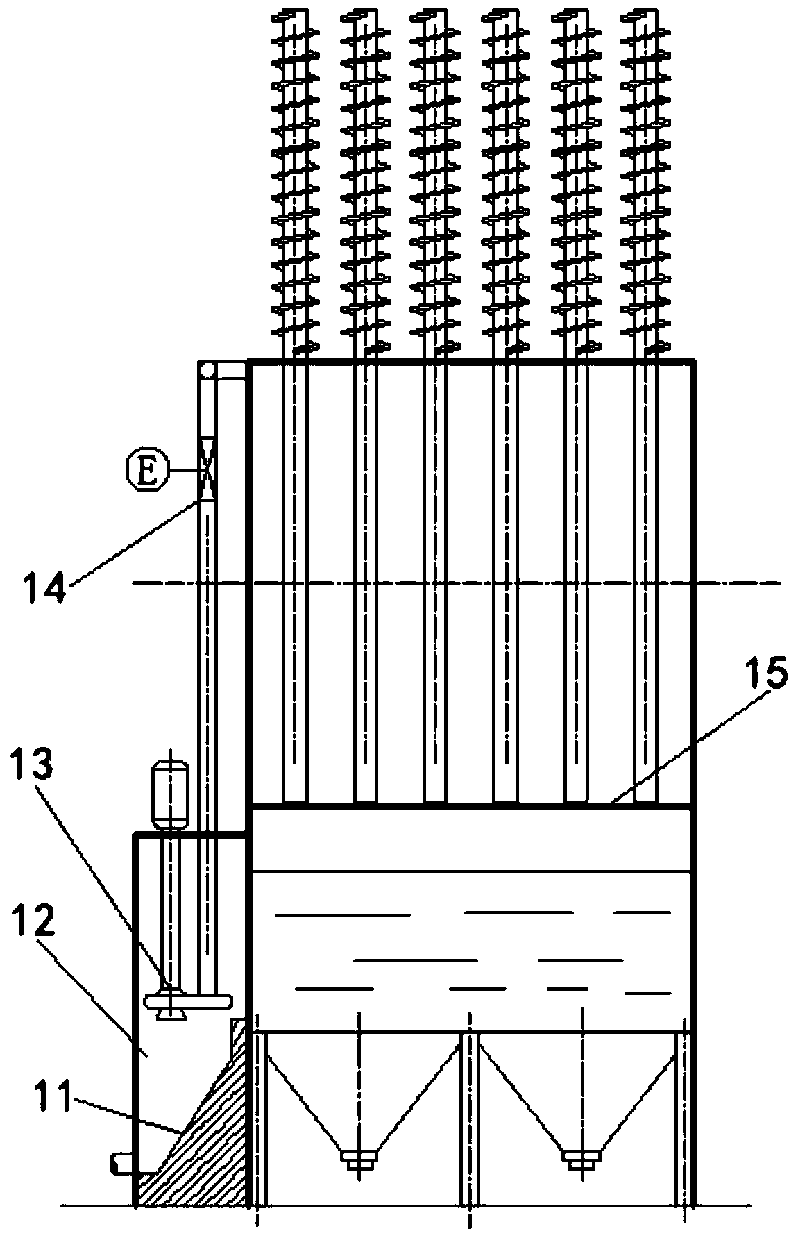
[0039] refer to Figure 1-2 , the flue gas terminal dehydration and fine dust removal device based on phase change in this embodiment includes:

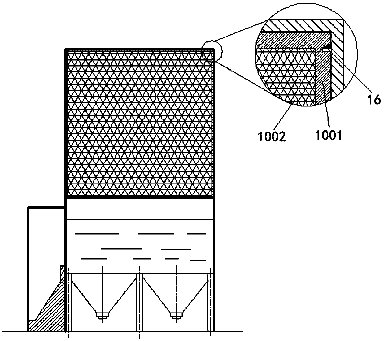
[0040] The dust removal box is arranged horizontally, one end of the dust removal box is connected with the flue gas inlet flue 1, and the other end of the dust removal box is connected with the flue gas outlet flue 5; The direction of the gas outlet flue 5 is successively provided with a phase change cooling zone 2, a spray cooling zone 3 and a filter dust removal zone 4; the phase change cooling zone 2 includes several layers of heat pipe heat exchange layers, and each layer of heat pipe heat exchange layers includes several parallel Arranged heat pipes, and the evaporation section of the heat pipe is located inside the dust removal box, and the condensation section of the heat pipe is located outside the dust removal box; the spray cooling area 3 includes several atomizing nozzles 301; the filter screen dust removal area 4 include...

Embodiment 2

[0047] The flue gas terminal dehydration fine dust removal device based on phase change in this embodiment has basically the same structure as that in Embodiment 2, further: the bottom of the sedimentation tank 6 is connected to several funnels 7, and the bottom of the funnel 7 is provided with a sealing plug 8 (Specifically in this embodiment, the sealing plug 8 is a pressure handle type rubber plug).

[0048] In this embodiment, several funnels 7 are connected to the bottom of the sedimentation tank 6, and the bottom of the funnel 7 is provided with a sealing plug 8. When the water in the sedimentation tank 6 accumulates to a certain extent, the seal at the bottom of each funnel 7 can be easily opened. The plug 8 discharges excess accumulated water, wherein the design of the funnel 7 is conducive to the sedimentation of the smoke and dust in the sedimentation tank 6 to fall into it due to sedimentation and be discharged.

Embodiment 3

[0050] The structure of the flue gas terminal dehydration and fine dust removal device based on phase change in this embodiment is basically the same as that of Embodiment 1, further: 1 place near the flue gas inlet flue and 5 places near the flue gas outlet flue on the dust removal box Observation holes 9 are respectively provided.

[0051] In this embodiment, observation holes 9 are respectively provided on the dust removal box near the flue gas inlet 1 and near the flue gas outlet flue 5, through which the dust removal and whitening effect of the flue gas in the dust removal box can be monitored. Carry out comparative observation and regular inspection and maintenance of the dust removal box; when the equipment has been running for a period of time, there is a small amount of sticky matter on the surface of the heat pipe and the surface of the filter screen 1002, and high-pressure water can be passed into the observation hole 9 to check the heat pipe and filter screen 1002. ...


PUM


Abstract

The invention discloses a phase change-based flue gas tail end dehydration fine dust removal device and relates to the field of air pollution control. The phase change-based flue gas tail end dehydration fine dust removal device comprises a horizontally arranged dedusting box body and a sedimentation tank, wherein a phase change cooling area, a spray cooling area and a filter screen dedusting areaare sequentially arranged in the dedusting box body from the flue gas inlet flue direction to the flue gas outlet flue direction. The phase change cooling area comprises a plurality of layers of heatpipe heat exchange layers, each layer of heat pipe heat exchange layer comprises a plurality of heat pipes which are arranged in parallel with each other, the evaporation sections of the heat pipes are positioned inside the dedusting box body, and the condensation sections of the heat pipes are positioned outside the dedusting box body. The spray cooling area comprises a plurality of atomizing nozzles. The filter screen dedusting area comprises a plurality of vertically arranged filter screen dust removal units, wherein each filter screen dust removal unit comprise a support frame, and the support frame is paved with a filter screen. The sedimentation tank is positioned below the opening on the bottom surface of the dedusting box body. The phase change-based flue gas tail end dehydrationfine dust removal device aims at further dedusting industrial flue gas under the conditions of low cost and low energy consumption to achieve near zero emission and eliminate white smoke.

Description

technical field [0001] The invention relates to the field of air pollution control, more specifically, to a phase change-based flue gas terminal dehydration fine dust removal device, which is suitable for industrial furnaces, especially for the treatment of industrial flue gas pollutants such as primary flue gas at the end of converter steelmaking . Background technique [0002] In recent years, with the gradual increase of my country's economic strength and stricter environmental protection standards, the emission standards of major pollutants have been subject to near-zero emission requirements. According to the national standard "Steelmaking Industry Emission Standard of Air Pollutants GB28664-2012", the emission concentration of primary flue gas particles from the intermediate converters of existing steelmaking enterprises is required to be 100mg / m 3 Below, newly established enterprises and enterprises with special emission limits require that the concentration of parti...

Claims


Application Information

Patent Timeline
Patent Type & Authority Applications(China)
IPC IPC(8): B01D50/00B01D53/26
CPCB01D53/265B01D2258/0283B01D50/60Y02A50/2351
Inventor 陈光王明月包向军周春林王芳张玉汪徽俊
Owner ANHUI UNIVERSITY OF TECHNOLOGY
Why Eureka
Try Eureka