Eureka AIR delivers breakthrough ideas for toughest innovation challenges, trusted by R&D personnel around the world.

Method for continuously separating CH4/CO2 by using fluidized bed

A CO2 and fluidized bed technology, applied in separation methods, chemical instruments and methods, dispersed particle separation, etc., can solve the problems of low mass transfer and heat transfer efficiency, long separation time, etc., and achieve easy control, uniform temperature, and cost reduction Effect

Active Publication Date: 2019-08-06
SOUTH CHINA UNIV OF TECH +1
View PDF10 Cites 3 Cited by
  • Summary
  • Abstract
  • Description
  • Claims
  • Application Information

AI Technical Summary

Problems solved by technology

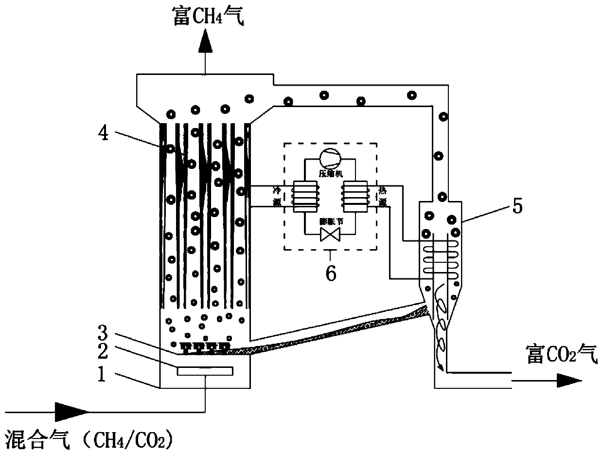
[0004] The purpose of the present invention is to overcome the defects of low mass and heat transfer efficiency and long separation time of the existing conventional tank reactor, and propose a method for continuously separating CH by using a fluidized bed. 4 / CO 2 The mixed gas method strengthens the mass transfer and heat transfer between the hydrate particles and the mixed gas, which is easy to control and improves the separation efficiency

Method used


Image

  • Method for continuously separating CH4/CO2 by using fluidized bed
  • Method for continuously separating CH4/CO2 by using fluidized bed

Examples


Embodiment 1

[0033] In this example, CH is carried out through the formation and decomposition of hydrate 4 / CO 2 Separation of mixture. Select 1.76wt% tetrabutylammonium bromide solution to separate CH 4 (67.00 mol%) / CO 2 (33.00 mol%), first set the operating temperature in the fluidized bed to 281.3K, where the mixed gas feed pressure is 1.14MPa, the flow rate is 1.5m / s, the working fluid flow rate is 0.3m / s, CH 4 Enriched in the fluidized bed gas phase. Using a heat pump to control the inner surface temperature of the cone of the cyclone separator to 298.15K, the hydrate decomposes, and the CO 2 It is enriched in the gas phase, while the working fluid flows into the fluidized bed reactor for recycling. It is calculated that under the above conditions, 90.38% CH can be produced continuously 4 and 71.51% CO 2 .

Embodiment 2

[0035] In this example, CH is carried out through the formation and decomposition of hydrate 4 / CO 2 Separation of mixture. Select pure aqueous solution to separate CH 4 (67.00 mol%) / CO 2 (33.00 mol%), first set the operating temperature in the fluidized bed to 278.15K, where the mixed gas feed pressure is 3MPa, the flow rate is 1.4m / s, the working fluid flow rate is 0.3m / s, CH 4 Enriched in the fluidized bed gas phase. Using a heat pump to control the inner surface temperature of the cone of the cyclone separator to 298.15K, the hydrate decomposes, and the CO 2 It is enriched in the gas phase, while the working fluid flows into the fluidized bed reactor for recycling. It is calculated that under the above conditions, 78.66% CH can be produced continuously 4 and 51.53% CO 2 .

Embodiment 3

[0037] In this example, CH is carried out through the formation and decomposition of hydrate 4 / CO 2 Separation of gas mixture. Select 0.293mol% tetrabutylammonium fluoride solution to separate CH 4 (50mol%) / CO 2 (50.00 mol%), first set the operating temperature in the fluidized bed to 278.15K, where the mixed gas feed pressure is 3MPa, the flow rate is 1.8m / s, the working fluid flow rate is 0.3m / s, CH 4 Enriched in the fluidized bed gas phase. Using a heat pump to control the inner surface temperature of the cone of the cyclone separator to 298.15K, the hydrate decomposes, and the CO 2 It is enriched in the gas phase, while the working fluid flows into the fluidized bed reactor for recycling. It is calculated that under the above conditions, 80.57% CH can be produced continuously 4 and 56.9% CO 2 .


PUM


Abstract

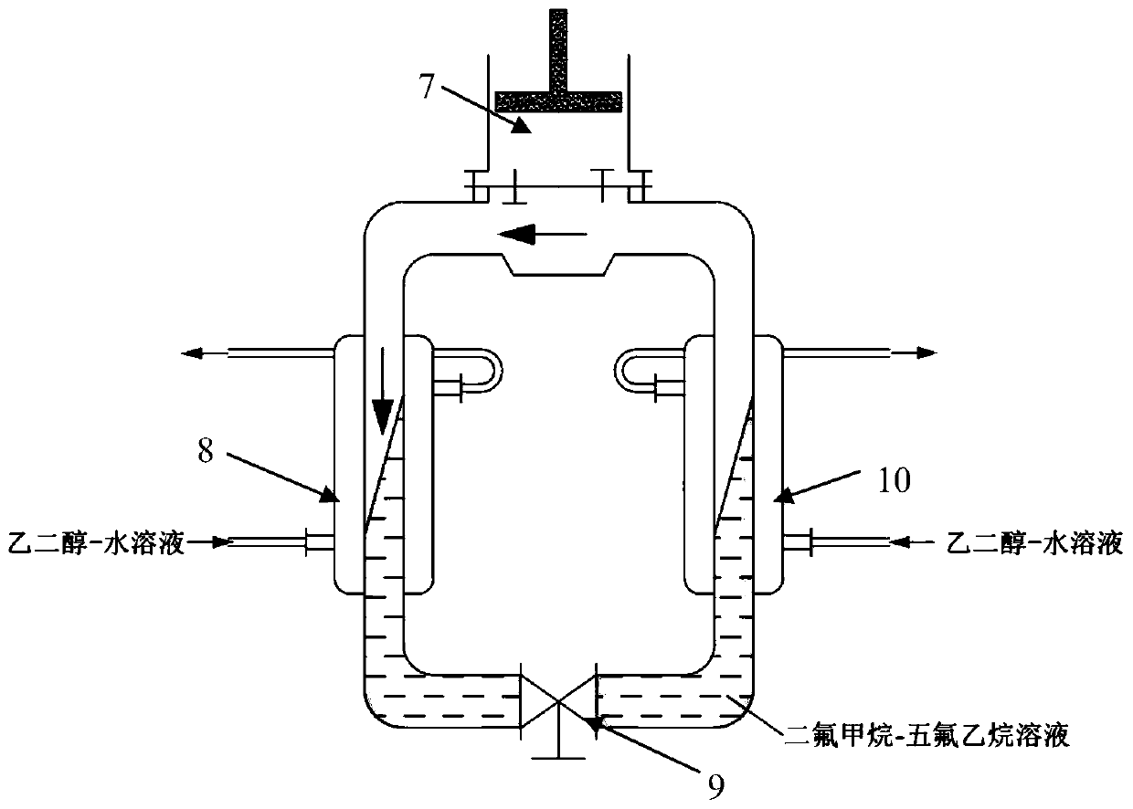
A method for continuously separating CH4 / CO2 by using a fluidized bed is achieved by a significant difference among pressures needed by different guest molecules to form hydrates at the same temperature. The mixed gas forms a hydrate in a fluidized bed reactor, the increasing mass and the arrangement of a variable diameter conduit for changing the flow rate push hydrate particles to move upwards,the temperature of the fluidized bed reactor is controlled to make CO2 in the mixed gas continuously form hydrate, and CH4 is enriched in the gas phase and flows out from the top of the fluidized bedto achieve the separation purpose. A heat pump technology is combined with the formation and decomposition of the hydrate to increase the energy utilization efficiency. A cold source is provided for the fluidized bed reactor to form the hydrate and produce a CH4-rich gas; and a heat source is provided for the cyclone separator to decompose the hydrate and produce a CO2-rich gas. The method forms aclean, efficient and environmentally-friendly separation method for the CH4 / CO2 mixed gas.

Description

technical field [0001] The invention relates to the field of mixed gas separation, in particular to a method for realizing continuous separation of CH by using a fluidized bed 4 / CO 2 Methods. Background technique [0002] CH 4 / CO 2 Mixed gas is the main component of oilfield associated gas, natural gas, biomass gas, etc. Under the general trend of promoting energy production and consumption revolution, research on CH 4 / CO 2 The separation of mixed gas is of great significance not only to slow down the global warming crisis, but also to promote my country's transition from traditional coal energy structure to natural gas energy. Combined with the analysis of the data of "China's Sustainable Development Strategy of Oil and Gas Resources", during the period from 2000 to 2013, the average annual growth rate of my country's natural gas production was about 7.5%, and my country's demand for natural gas from the overall The average annual growth rate is about 10.8%. It is...

Claims


Application Information

Patent Timeline
Patent Type & Authority Applications(China)
IPC IPC(8): B01D53/78B01D53/96B01D53/62
CPCB01D53/62B01D53/78B01D53/96B01D2257/504Y02C20/40
Inventor 樊栓狮尤莎莉郎雪梅王燕鸿李遵照薛倩王晓霖孟凡飞王海波
Owner SOUTH CHINA UNIV OF TECH
Why Eureka
Eureka Blog
Learn More