
A nitrogen-containing treatment and discharge system for coating wastewater

A technology for coating wastewater and discharge system, which is applied in the field of energy-saving sewage treatment system and nitrogen-containing treatment and discharge system of coating wastewater, which can solve the environmental occasions that cannot use a large amount of treatment, the treatment of organic matter is not thorough enough, and the circulation system is few, etc. problems, achieve good activity and intermittent variability, optimal aeration decomposition effect, and reduce maintenance costs.

Active Publication Date: 2022-07-12
江苏尚裕润环保工程有限公司
View PDF9 Cites 0 Cited by
  • Summary
  • Abstract
  • Description
  • Claims
  • Application Information

AI Technical Summary

Problems solved by technology

[0002] At present, coating the product can improve the anti-oxidation and corrosion resistance of the product surface, and isolate the product from external water and air through coating. However, during the coating process, a large amount of wastewater will be generated. The coating wastewater contains Pollutants include surfactants, oils, pigments, organic solvents, heavy metals and phosphates, etc. Therefore, the coating sewage needs to be treated before it can be discharged. If it is discharged directly, it will cause problems such as water quality deterioration and environmental pollution, especially in some industrial parks. Automobile manufacturing plants, such as more than 90% of the outer surfaces of automobiles and motorcycles, need to be painted. The painting of automobile bodies and parts is one of the links that produce the most types of pollutants and the largest amount of wastewater discharge in the production of the automobile industry. The amount of waste water discharged from the installation is large, and the amount that needs to be treated frequently is also large. At the same time, with the improvement of the environment in our country, more and more companies have begun to pay attention to the treatment of painting waste water. The existing treatment process of automobile painting waste water is relatively complicated. , the structure of the automobile painting wastewater treatment system is relatively complex, and it is not convenient for the treatment of automobile painting wastewater. Driven by energy, and the coating wastewater is directly treated, the processing load of the equipment increases, and the treatment effect decreases
[0003] Publication No. 201520253950.5 discloses a coating sewage treatment equipment, which adopts a combination of physical and chemical means, sets up multi-layer filter screens for physical filtration, and uses flocculants and defoamers to treat sewage, and in the circulation pool Activated carbon for adsorption and filtration is installed in the utility model. Although the structure of this utility model is simple and the cost is low, the treatment of organic matter is not thorough enough, and it can only meet the standard of circulating water, but not the standard of discharge. There is only one storage tank above the sedimentation tank and the secondary sedimentation tank. The reagents need to be manually prepared and placed in the storage tank. The workload is large, the daily processing volume is small, and it is not possible to use the environment with a large processing capacity.
Publication No. CN107265787A discloses an automobile painting wastewater treatment process and an automobile painting wastewater treatment system, including a pretreatment step, a coagulation reaction step, a precipitation removal step, a hydrolysis acidification step and a molecular decomposition step. There are few internal circulation systems in the system, Some beneficial factors have not been collected and reused, and the collection action for sedimentation is poor, the sewage flow mode is single, and the filtration, reaction time and effect are poor

Method used


Image

  • A nitrogen-containing treatment and discharge system for coating wastewater
  • A nitrogen-containing treatment and discharge system for coating wastewater

Examples


Embodiment Construction

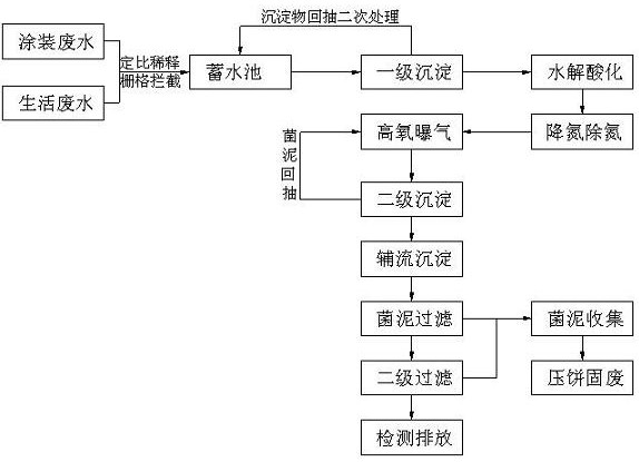
[0054] A nitrogen-containing treatment and discharge system for coating wastewater according to the present invention is realized as follows, including a water storage tank (1), a sedimentation tank (2), a hydrolysis and acidification tank (3), an anaerobic tank (4), and an aeration tank (5). ), auxiliary flow sedimentation tank (6), filter tank (7), sand filter tank (8), detection tank (9), bacterial sludge sedimentation tank (10) and sludge collection tank (11), the reservoir ( 1) Two liquid accommodating areas are provided, and the two liquid accommodating areas are respectively provided with an introduction pipe and a discharge pipe, the introduction pipe of the reservoir (1) is provided with an intercepting grid, and the discharge pipe on the reservoir (1) The sedimentation tank (2) is communicated with the sedimentation tank (2) through a high-pressure pump. The sedimentation tank (2) is in and out from the bottom, and the pool walls around the bottom of the sedimentation...


PUM

PropertyMeasurementUnit
thicknessaaaaaaaaaa
thicknessaaaaaaaaaa

Abstract

The invention discloses a nitrogen-containing treatment and discharge system for coating wastewater. Disclosed is a method of diluting coating wastewater with domestic sewage, setting up a sedimentation tank with a high tower structure, utilizing the water level difference for self-flow, and combining the internal recycling system for effective bacterial sludge. It is an energy-saving sewage treatment system that can be recycled, and can collect sediments in a centralized manner, and collect sewage treatment and other wastes in the production line. The inlet pipe and the discharge pipe are respectively provided in the area, the inlet pipe of the storage tank is provided with an intercepting grid, and the discharge pipe on the storage tank is communicated with the sedimentation tank through a high-pressure pump. The walls of the surrounding pools are provided with water collecting tanks for guiding water and sludge, and a plurality of trapezoidal mud buckets are arranged at the bottom of the sedimentation tank. There is a straight valve.

Description

technical field [0001] The invention relates to a nitrogen-containing treatment and discharge system for coating wastewater, which relates to a structure for air blowing and cleaning the molding jacket remaining on the core-pulling structure during mold production, and belongs to the field of sewage treatment. In particular, it relates to a kind of domestic sewage to dilute coating sewage, set up a sedimentation tank with a high tower structure, use the water level difference for self-flow, and combine the internal recycling system to recover the effective bacterial sludge, and can collect the sediment in a centralized manner. Energy-saving sewage treatment system for sewage treatment and collection of other wastes from production lines. Background technique [0002] At present, coating the product can improve the anti-oxidation and corrosion resistance of the product surface. The product is isolated from the external water and gas by coating. However, during the coating pro...

Claims


Application Information

Patent Timeline
Patent Type & Authority Patents(China)
IPC IPC(8): C02F9/14C02F101/16
CPCC02F9/00C02F1/001C02F1/40C02F1/66C02F1/52C02F1/5236C02F1/56C02F2001/007C02F3/30C02F1/283C02F7/00C02F2301/08C02F2303/16C02F3/34C02F2101/163C02F2101/166Y02W10/10
Inventor 不公告发明人
Owner 江苏尚裕润环保工程有限公司
Learn More