
Multilayer structure with vertical magnetic anisotropy at interface and magnetic random access memory

An anisotropic, perpendicular magnetic technology, applied in the fields of devices applying electro-magnetic effects, parts of electromagnetic equipment, and manufacturing/processing of electromagnetic devices, etc., can solve the problem of low storage density, reduced thermal stability, problems such as low thermal stability, to achieve the effect of enhancing the perpendicular magnetic anisotropy of the interface, good thermal stability, and promoting the formation of crystal orientations

Active Publication Date: 2019-08-06
BEIHANG UNIV
View PDF13 Cites 3 Cited by
  • Summary
  • Abstract
  • Description
  • Claims
  • Application Information

AI Technical Summary

Problems solved by technology

[0006] However, the structure of Ta(Mo,Hf) / CoFeB / MgO / CoFeB / Ta(Mo,Hf) still has obvious shortcomings
First, the interface perpendicular magnetic anisotropy of the structure is weak, resulting in low thermal stability of the structure; secondly, because of the weak interface perpendicular magnetic anisotropy, in order to make the easy axis of magnetization perpendicular to the interface direction, it is necessary A thinner CoFeB layer reduces the demagnetization field, which leads to a larger magnetic damping coefficient and thus a larger critical switching current for the structure
Finally, the thermal stability will decrease when the cross-sectional size is reduced. In order to maintain sufficient thermal stability, the size of the structure will be increased, which will lead to a lower storage density of the MRAM using this structure.

Method used


Image

  • Multilayer structure with vertical magnetic anisotropy at interface and magnetic random access memory
  • Multilayer structure with vertical magnetic anisotropy at interface and magnetic random access memory
  • Multilayer structure with vertical magnetic anisotropy at interface and magnetic random access memory

Examples


Embodiment Construction

[0020] In order to make the purpose, technical solutions and advantages of the embodiments of the present invention clearer, the technical solutions in the embodiments of the present invention will be clearly and completely described below in conjunction with the drawings in the embodiments of the present invention. Obviously, the described embodiments It is a part of embodiments of the present invention, but not all embodiments. Based on the embodiments of the present invention, all other embodiments obtained by persons of ordinary skill in the art without creative efforts fall within the protection scope of the present invention.

[0021] In the description of the embodiments of the present invention, it should be noted that the terms "center", "upper", "lower", "left", "right", "vertical", "horizontal", "inner", "outer " and other indicated orientations or positional relationships are based on the orientations or positional relationships shown in the drawings, and are only ...


PUM

PropertyMeasurementUnit
Thicknessaaaaaaaaaa
Thicknessaaaaaaaaaa
Thicknessaaaaaaaaaa

Abstract

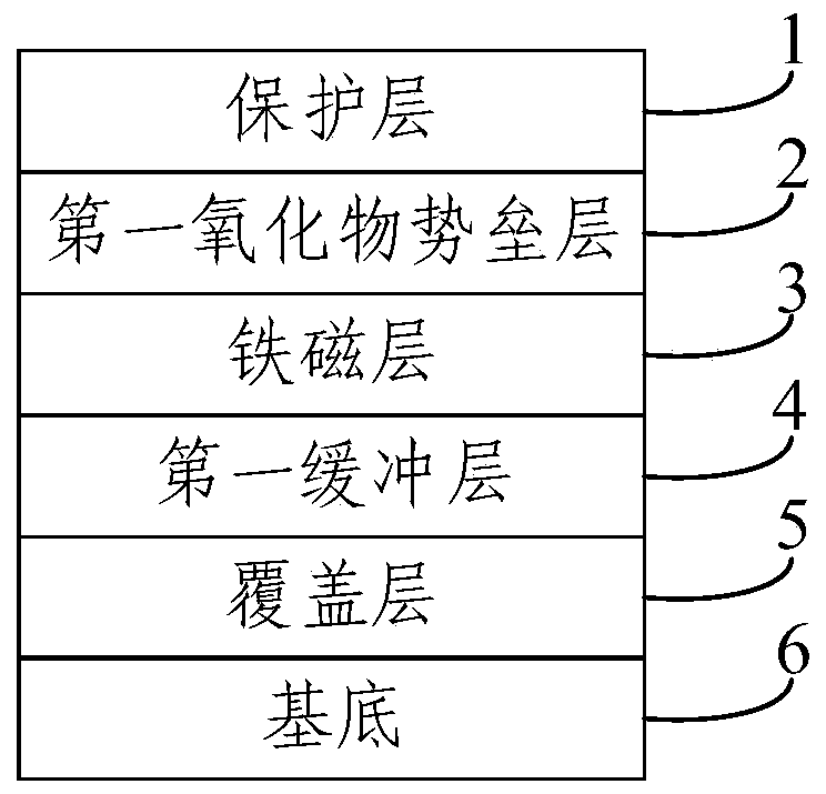
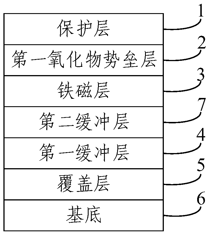
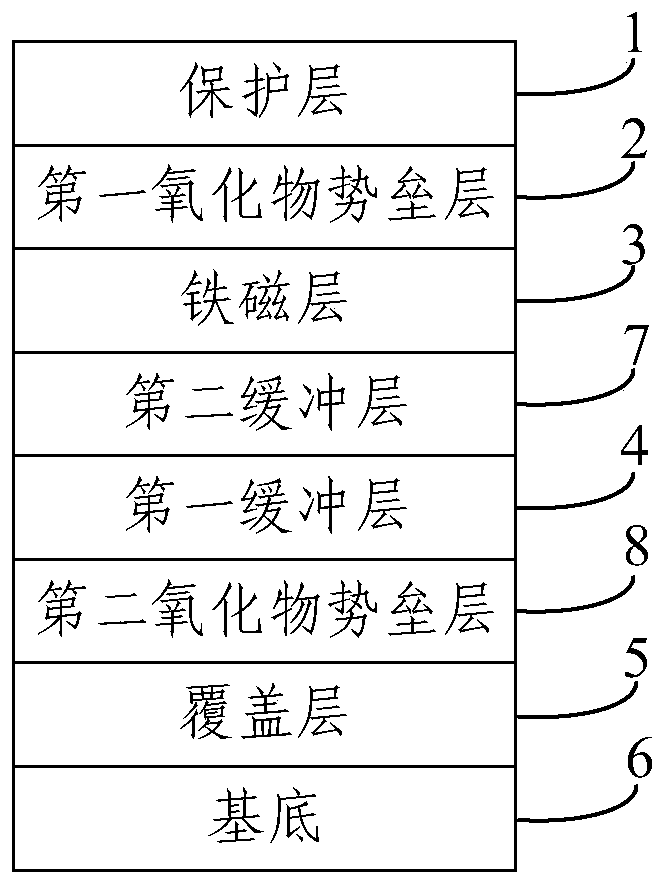
The embodiment of the invention provides a multilayer structure with vertical magnetic anisotropy at the interface and a magnetic random access memory. The whole multilayer structure is annealed at atemperature of above 500 DEG C after growth, which ensures good thermal stability. In the annealing process, the crystallization of chromium metal in a buffer layer promotes the formation of the crystal orientation of the whole structure. At the same time, charge trapping is formed between a ferromagnetic layer and a first oxide barrier layer due to annealing, which enhances the vertical magneticanisotropy at the interface formed by interlayer coupling between the two layers. Because the layers are at a nanometer scale, the obtained multilayer structure also has the advantage of small size. The magnetic tunnel junction in the magnetic random access memory provided by the embodiment of the invention is a multilayer structure with vertical magnetic anisotropy at the interface, which can increase the storage density of the magnetic random access memory.

Description

technical field [0001] The invention relates to the technical field of magnetic random access memory, and more specifically, relates to a multi-film layer structure with interface perpendicular magnetic anisotropy and magnetic random access memory. Background technique [0002] At present, magnetic random access memory (MRAM) and magnetic logic have the advantages of non-volatility, fast read and write speed, low power consumption and unlimited erasing and rewriting, and have attracted extensive attention from industry and academia. [0003] The core device of magnetic random access memory and magnetic logic is the magnetic tunnel junction (Magnetic Tunnel Junction, MTJ). The basic structure of the magnetic tunnel junction is a three-layer thin film structure, which specifically includes: a reference layer, a barrier layer and a free layer. Wherein, both the reference layer and the free layer are ferromagnetic materials. When the magnetization directions of the two layers a...

Claims


Application Information

Patent Timeline
IPC IPC(8): H01L43/00H01L43/02H01L43/12H10N50/01H10N50/80
CPCH10N50/00H10N50/80H10N50/01
Inventor 聂天晓李晓辉查丹
Owner BEIHANG UNIV
Learn More