Microsphere coating device capable of timely chip removal

A coating device and technology for microspheres, applied in coating, metal material coating process, vacuum evaporation plating, etc., can solve the problems of uneven wall thickness of microspheres, spending a lot of time vacuuming, cracking, etc., to avoid The effect of coating overgrowth

Active Publication Date: 2021-05-18
LASER FUSION RES CENT CHINA ACAD OF ENG PHYSICS
View PDF5 Cites 0 Cited by
  • Summary
  • Abstract
  • Description
  • Claims
  • Application Information

AI Technical Summary

Problems solved by technology

[0005] First, when the coating time is long, small particles sputtered from the target are inevitable
In addition, slag, chips, debris, etc. are easy to fall off the wall of the vacuum chamber, and they gradually accumulate in the rebounding disk, which not only affects the random rotation of the microspheres, but also the smaller particles are easy to be embedded and grow.
Unsmooth rotation will lead to uneven wall thickness of microspheres, and entrapment growth will form nodules on the surface of microspheres, which will reduce the quality of microsphere coating
[0006] Second, as the thickness of the coating increases, the growth stress mismatch between the rebounding disk and the coating material will cause the coating inside the disk to wrinkle, crack, or even fall off, etc., which will also hinder the random rolling of the microspheres, resulting in the coating Inhomogeneous layer wall thickness reduces microsphere quality
[0007] Third, the traditional coating disc is a solid disc, which cannot remove chips in time, and needs to interrupt the coating for manual replacement
The replacement process will inevitably expose the microspheres to the atmosphere, and the possibility of surface oxidation and contamination will increase. Continued coating will reduce the quality of the microspheres
In addition, after replacing the rebound disc, in addition to bringing additional workload to the experimenter, it takes a lot of time to vacuumize, which undoubtedly prolongs the preparation cycle of the microspheres

Method used


Image

  • Microsphere coating device capable of timely chip removal
  • Microsphere coating device capable of timely chip removal

Examples


Embodiment 1

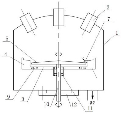
[0025] Embodiment 1: see figure 1 and figure 2 , a microsphere coating device capable of timely chip removal, comprising a vacuum chamber 1, a magnetron target gun 2 and a coating disk, the coating disk includes an outer cylinder and an inner turntable 5 arranged coaxially;

[0026] The outer cylinder is horizontally fixed in the vacuum chamber 1 and is composed of a bottom plate 3 and an annular body 4 on the bottom plate 3;

[0027] The inner turntable 5 is in the shape of a cone with a small top and a large bottom, and a magnetic coupler is provided at the bottom. The magnetic coupler is used to couple the motor outside the vacuum chamber 1 to drive the inner turntable 5 to rotate along the central axis of the inner turntable 5;

[0028] The bottom of the inner turntable 5 is not in contact with the bottom plate 3, and the edge of the inner turntable 5 is not in contact with the inner wall of the annular body 4 and forms an annular groove 6, the gap between which is small...

Embodiment 2

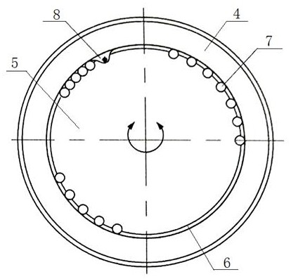
[0030] Embodiment 2: The inner wall of the annular body 4 above the inner turntable 5 is also provided with a paddle 8 for adjusting the posture of the microsphere 7, and the rest is the same as that of the embodiment 1. The purpose of the paddle 8 is to adjust the posture of the microsphere. When the microsphere rotates once a week, the posture will be adjusted once through the paddle 8, which is used to stimulate the random rotation of the microsphere 7, thereby avoiding the simple and periodic rotation in the prior art. The problem of uneven coating caused by rolling. When the present embodiment is working, it can be rotated in any mode, evenly, and with variable speed.

Embodiment 3

[0031] Embodiment 3: The inner wall of the annular body 4 above the inner turntable 5 is also provided with a paddle 8 for moving the microsphere 7 to adjust the attitude of the microsphere 7 , and the bottom plate 3 is provided with several chip discharge ports 9 . All the other are identical with embodiment 1. On the basis of Embodiment 1, the present invention adds a chip discharge port 9, so that the falling slag chips can not only enter the gap between the inner turntable 5 and the bottom plate 3, but also fall down through the chip discharge port 9 and enter the In vacuum chamber 1.


PUM

PropertyMeasurementUnit
diameteraaaaaaaaaa

Abstract

The invention discloses a microsphere coating device capable of removing chips in time, comprising a vacuum chamber, a magnetron target gun and a coating disk, the coating disk includes an outer cylinder and an inner turntable coaxially arranged; the outer The cylinder is horizontally fixed in the vacuum chamber. The inner turntable is in the shape of a cone with a small top and a large bottom. The bottom is equipped with a magnetic coupler. The magnetic coupler is used to couple the motor located outside the vacuum chamber to drive the central axis of the inner turntable. Rotation; the bottom of the inner turntable is not in contact with the bottom plate, the edge of the inner turntable is not in contact with the inner wall of the ring and forms an annular groove, and the gap between the ring grooves is smaller than the diameter of the microsphere. The invention breaks through the limitations of the traditional solid-coated disc slag removal technology, and adopts the structure of an outer cylinder and an inner turntable arranged coaxially but with a certain gap, and then matched with a paddle. Not only can it be coated uniformly for a long time, but also can remove chips in time to avoid adhesion between chips and microspheres, thereby improving the quality of microsphere coatings and shortening the target making cycle.

Description

technical field [0001] The invention relates to the field of laser inertial confinement fusion target making equipment, in particular to a microsphere coating device capable of timely chip removal. Background technique [0002] In the laser inertial confinement fusion (ICF: Inertial Confinement Fusion) target making process, microspheres are often used for the determination of various physical parameters, such as symmetric compression, ablation rate, RT instability growth, radiation opacity and compression ratio determination, etc. . Therefore, the preparation of microspheres is indispensable. How to prepare dense microspheres with uniform wall thickness, in addition to the distribution and position of the sputtering target gun, the design of the rebound plate is very important. [0003] Taking the traditional magnetron sputtering microsphere coating device as an example, the target gun is fixed on the top of the vacuum chamber, and the coating disk is installed at the foc...

Claims


Application Information

Patent Timeline
Patent Type & Authority Patents(China)
IPC IPC(8): C23C14/35C23C14/50
CPCC23C14/35C23C14/505
Inventor 罗炳池李恺何玉丹李文琦张吉强陈龙金雷罗江山李波
Owner LASER FUSION RES CENT CHINA ACAD OF ENG PHYSICS
Why Eureka
Try Eureka