
Flue gas discharge subsystem of residential flue gas emission system

A smoke emission and subsystem technology, applied to vertical pipes, building components, fire protection, etc., can solve the problems affecting the fire spread of check valves, lack of sealing devices, and inapplicability, so as to improve the prevention of smoke backflow and construction The effect of convenience and easy installation

Inactive Publication Date: 2019-08-20
徐仁春
View PDF9 Cites 0 Cited by
  • Summary
  • Abstract
  • Description
  • Claims
  • Application Information

AI Technical Summary

Problems solved by technology

Utility model patent CN201344718Y discloses a high-temperature-resistant and corrosion-resistant concrete air duct, but the utility model patent relates to a "high-temperature-resistant and corrosion-resistant concrete air duct applied in the main kiln wall of the tunnel kiln in the building materials industry", It should be said that this prior art is not suitable for residential smoke exhaust systems
It is obviously difficult to effectively prevent the spread of fire by relying solely on the force of the blades to hang freely in the existing check valves. A small number of check valves are equipped with tension springs, but manual control is required, and it is difficult to prevent the spread of fire in a timely and effective manner.
The contact surface between the existing check valve and the wall lacks the necessary sealing device, which also greatly affects the effect of the check valve on preventing the spread of fire

Method used


Image

  • Flue gas discharge subsystem of residential flue gas emission system
  • Flue gas discharge subsystem of residential flue gas emission system
  • Flue gas discharge subsystem of residential flue gas emission system

Examples


Embodiment 1

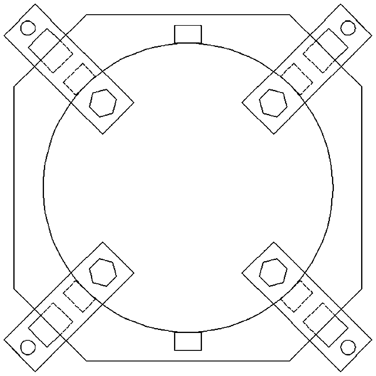
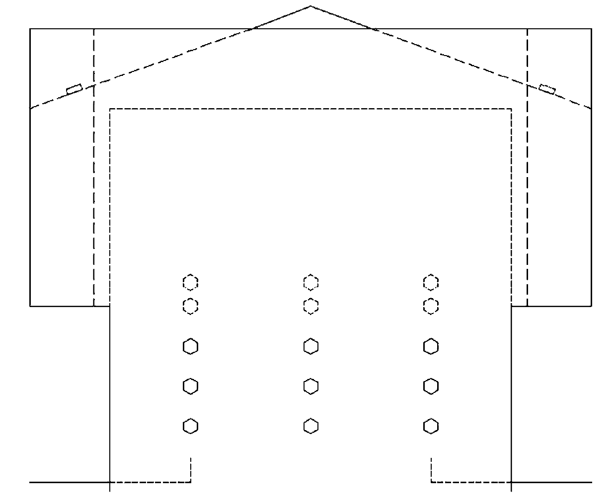
[0030] like Figure 5 and 6 As shown, a residential flue gas discharge system includes a flue gas input subsystem, a flue gas delivery subsystem, and a flue gas output subsystem arranged in sequence, and the junction between the flue gas input subsystem and the flue gas delivery subsystem is set There are fixing holes for placing heat-resistant and fireproof check valves and composite fixtures for fixing the check valves; the flue gas delivery subsystem includes composite flue gas exhaust ducts such as Figure 7 As shown, the composite reserved holes and composite connecting sleeves of cast-in-place slabs are as follows Figure 10 shown;

[0031] The flue gas output subsystem includes a composite cast-in-place roof reserved hole 9, a composite connecting sleeve such as Figure 10 as shown and an inert windshield such as figure 2 and 8 Shown one end is arranged on the support cylinder 13 of building object top, is positioned at described support cylinder other end radial ...

Embodiment 2

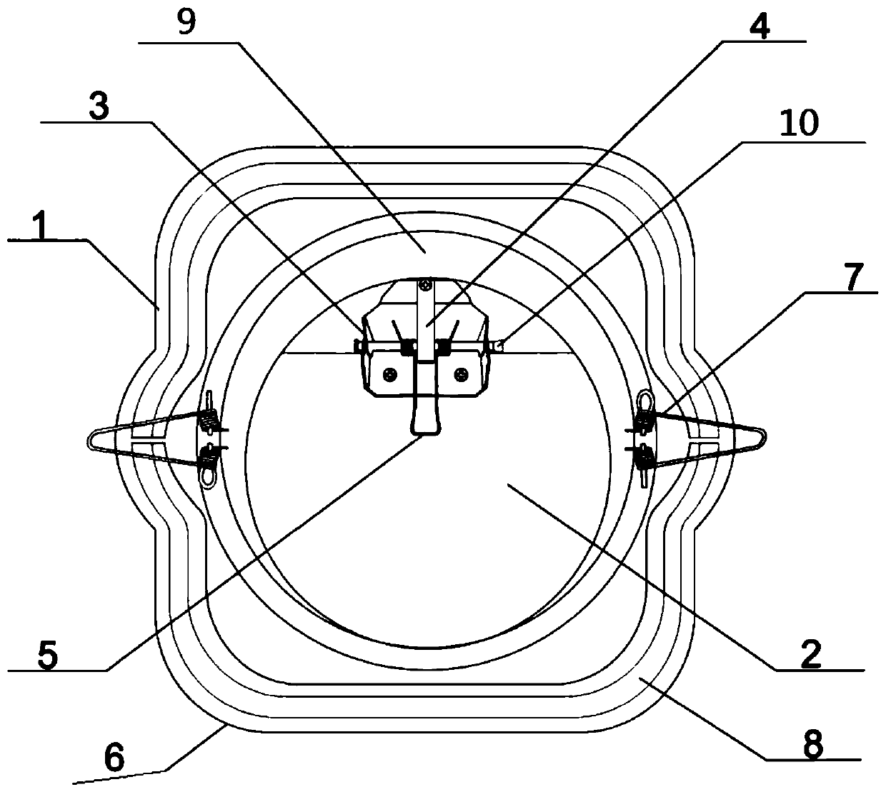
[0037] like figure 1 As shown, the fire check valve in the technical solution of the present invention includes a base 1, a ventilation pipe 9, a hinge 3, a valve plate 2, a temperature sensing plate 4 and an extension spring 5, and the ventilation pipe 9 is installed on the base On the seat 1, the valve sheet 2 is flexibly connected to the ventilation pipe 9 through the hinge 3, the temperature sensing sheet 4 is connected to the hinge 3, and the hinge 3 is provided with a hinge connection. Shaft 10, the extension spring 5 is sleeved on the hinge connecting shaft 10, and a layer of anti-corrosion layer 6 is coated on the base 1.

[0038] The fire check valve also includes a snap ring 7 connected to the base 1 .

[0039] The inner surface of the base 1 is connected with a flame-retardant sealing strip 8, and the shape of the flame-retardant sealing strip 8 is adapted to the shape of the inner surface of the base 1.

Embodiment 3

[0041] Preparation of composite flue gas exhaust duct:

[0042] Composite flue gas exhaust duct of the present invention Made from the following raw materials in parts by weight:

[0043] Aggregate, gypsum, lime calcium powder, toughening agent, interface modifier, flame retardant and foaming agent.

[0044]The aggregate is any one or a mixture of diatomite, slag powder, fly ash, expanded vermiculite, and vitrified microbeads. The gypsum is desulfurized gypsum.

[0045] The toughening agent is any one of calcium carbonate whiskers, potassium carbonate whiskers, and magnesium salt whiskers.

[0046] The interface modifier is a mixture of mica flakes, gelling agent and silicon powder.

[0047] The content ratio of mica sheet, gelling agent and silicon powder in the interface modifier is 3:1:0.02.

[0048] The flame retardant is any one of antimony trioxide, magnesium hydroxide and aluminum hydroxide.

[0049] The blowing agent is sodium lauryl sulfate.

[0050] Flame-ret...


PUM


Abstract

The invention provides a glue gas discharge subsystem of a residential flue gas emission system. The flue gas discharge subsystem of the residential flue gas emission system comprises a combined cast-in-place roof preformed hole, a combined connection sleeve and an inertia wind-proof cap. The wind-proof cap is provided with a supporting cylinder with one end located on the roof of a building, a wind-proof cylinder located on the radial outer side of the other end of the supporting cylinder and a wind-proof shield assembly arranged in the wind-proof cylinder. An air duct installation assembly is arranged at the connection position between an exhaust pipeline of the subsystem and the floor slab of the building. The installation assembly comprises a connection sleeve pipe and a connection sleeve plate, wherein the diameters of the two ends of the connection sleeve pipe are identical with the inner diameter of the floor slab preformed hole, the middle portion of the connection sleeve pipeis provided with a square outside and a circular inside, and the connection sleeve plate is provided with a square outside and an circular inside. The inner diameter of the circle of the sleeve platewhich is provided with the square outside and the circular inside is equal to the outer diameter of the connection sleeve pipe.

Description

technical field [0001] The invention relates to a gas discharge system, in particular to a smoke output subsystem of a residential smoke discharge system. Background technique [0002] With the rapid development of urbanization and the continuous improvement of people's living standards, higher requirements are put forward for living conditions and living environment. New houses must ensure that the exhaust gas in houses such as kitchens and bathrooms in the houses will not cause environmental pollution. Existing residential flue gas discharge system generally comprises the horizontal exhaust input duct of every household in the dwelling house, the output part of vertical conveying duct and roof part. However, the prior art discloses the materials of each part of the flue gas system. For example, the CN2436798Y utility model patent discloses a vertical smoke exhaust duct for residential kitchens and bathroom detachable check valves, and also discloses vertical The technical...

Claims


Application Information

Patent Timeline
Patent Type & Authority Applications(China)
IPC IPC(8): E04F17/02E04B1/94
CPCE04F17/02E04F17/026E04B1/948
Inventor 龚携轩喻适之
Owner 徐仁春
Learn More