
Dynamic simulation prediction method for machining gap and erosion removal rate in rotary printing electrolytic machining process

A processing gap and dynamic simulation technology, which is applied in the direction of electric processing equipment, electrochemical processing equipment, processing special circuits, etc., can solve problems such as large amount of calculation, slow solution process, and many iteration steps

Active Publication Date: 2019-08-23
NANJING UNIV OF AERONAUTICS & ASTRONAUTICS
View PDF7 Cites 9 Cited by
  • Summary
  • Abstract
  • Description
  • Claims
  • Application Information

AI Technical Summary

Problems solved by technology

However, the finite element method is used to solve the electrolytic machining process, the number of iteration steps is large, the calculation amount is large, and the solution process is slow
In addition, in spin printing electrolytic machining, the anode of the workpiece and the cathode of the tool are both annular rotating bodies, which is very different from traditional electrolytic machining.

Method used


Image

  • Dynamic simulation prediction method for machining gap and erosion removal rate in rotary printing electrolytic machining process
  • Dynamic simulation prediction method for machining gap and erosion removal rate in rotary printing electrolytic machining process
  • Dynamic simulation prediction method for machining gap and erosion removal rate in rotary printing electrolytic machining process

Examples


Embodiment Construction

[0058] The specific embodiments of the present invention will be described in further detail below in conjunction with the accompanying drawings of the specification.

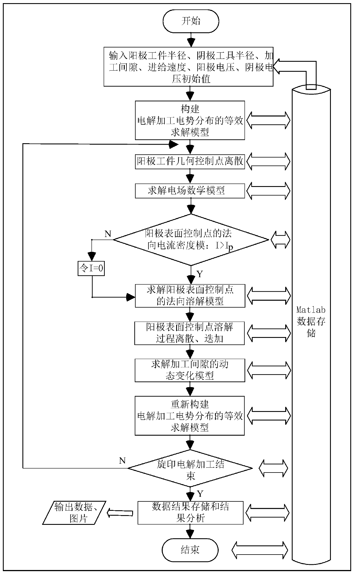
[0059] Such as figure 1 As shown, the present invention designs a dynamic simulation prediction method for machining gap and erosion speed during spin electrochemical machining. In actual application, it specifically includes the following steps:

[0060] The specific design steps are as follows:

[0061] Step 1. Determine according to electrochemical machining requirements: the initial radius of the workpiece anode R a , The initial radius of the cathode tool R c , Initial machining gap G 0 , Workpiece anode surface voltage U a , Cathode tool surface voltage U c , Workpiece anode and cathode tool speed w, workpiece anode per revolution of radial erosion Δr, cathode tool feed rate v 0 , Along any section, divide the circumference of the anode surface of the circular workpiece into N points to form the contour control ...


PUM


Abstract

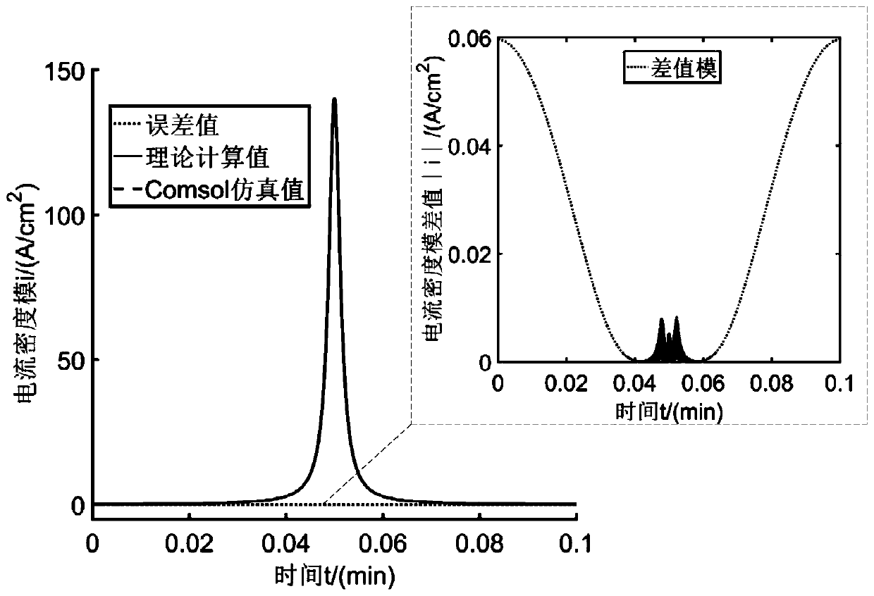
The invention discloses a dynamic simulation prediction method for a machining gap and an erosion removal rate in a rotary printing electrolytic machining process, and belongs to the technical field of electrolytic machining. According to the method, an actual rotary printing electrolytic machining process is simulated by establishing a dissolution model of a material on surface of a workpiece anode; an analytical solution of current density of any point on the surface of the workpiece anode is solved by utilizing a laplacian equation of complex fractional linear mapping; each circle of machining process of the workpiece anode is dispersed into a plurality of extremely small time periods by adopting a discrete method, and the erosion removal thickness of the material on the surface of theworkpiece anode is reduced along the radial direction; and the discrete and iterative simulation of Matlab are used to solve the dynamic change values of the machining gap and the erosion removal rateof the anode surface material after one circle. In the actual rotary printing electrolytic machining process, the optimal electrolytic machining process parameters can be obtained by means of the method, test time is greatly saved, and theoretical guidance is provided for selection of rotary printing electrolytic machining parameters.

Description

Technical field [0001] The invention relates to a dynamic simulation prediction method of machining gap and erosion rate during spin-print electrochemical machining, and belongs to the field of electrochemical machining. Background technique [0002] In the machinery manufacturing industry, take the aircraft engine casing as an example. Its wall thickness is usually 1-3mm. Traditional machining is used. The workpiece is easily deformed, the residual stress is large, the tool wear is serious, the processing cycle is long, and the processing cost is high; With the chemical milling method, the uniformity and roughness of the thin-walled parts are difficult to guarantee, and the strong acid corrosion solution used has great environmental pollution. The high-precision machining of thin-walled casing has become a bottleneck restricting the development and production of aero-engines. [0003] Electrochemical machining is based on electrochemical anode dissolution and removal of workpiece...

Claims


Application Information

Patent Timeline
IPC IPC(8): B23H3/00B23H3/02G16C20/10
CPCB23H3/00B23H3/02G16C20/10
Inventor 曹文见王登勇朱荻朱增伟何斌方忠东
Owner NANJING UNIV OF AERONAUTICS & ASTRONAUTICS
Learn More