
Asphalt mixing plant tail gas white smoke eliminating treatment apparatus

A treatment device and asphalt mixing station technology, applied in gas treatment, dispersed particle separation, membrane technology, etc., can solve the problems of non-energy-saving and environmental protection of asphalt flue gas, ineffective treatment effect, single asphalt flue gas treatment method, etc.

Pending Publication Date: 2019-08-30
JIANGSU MODERN ROAD & BRIDGE
View PDF0 Cites 3 Cited by
  • Summary
  • Abstract
  • Description
  • Claims
  • Application Information

AI Technical Summary

Problems solved by technology

[0004] The purpose of the present invention is to provide a whitening treatment device for the tail gas of an asphalt mixing station, so as to solve the technical problems in the prior art that the asphalt fume is treated in a single way, the treatment effect is not obvious, and the treatment of asphalt fume is not energy-saving and environmentally friendly.

Method used


Image

  • Asphalt mixing plant tail gas white smoke eliminating treatment apparatus
  • Asphalt mixing plant tail gas white smoke eliminating treatment apparatus
  • Asphalt mixing plant tail gas white smoke eliminating treatment apparatus

Examples


Embodiment 1

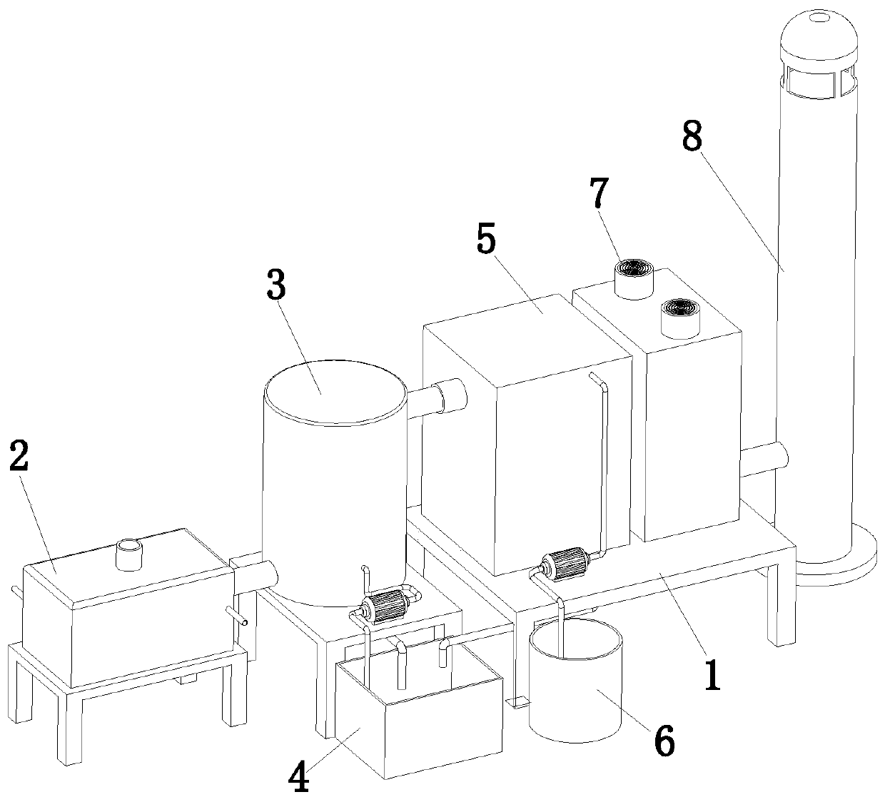
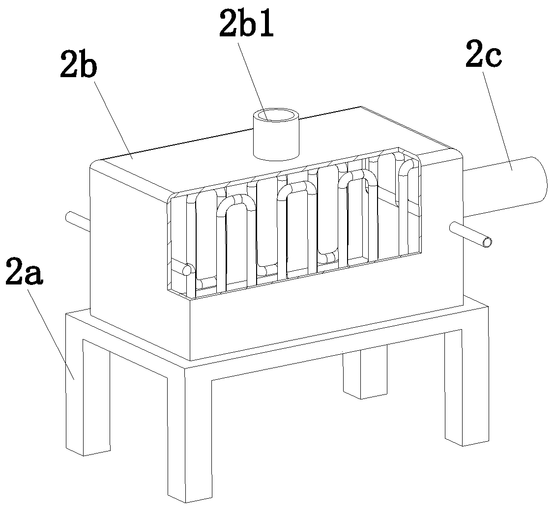
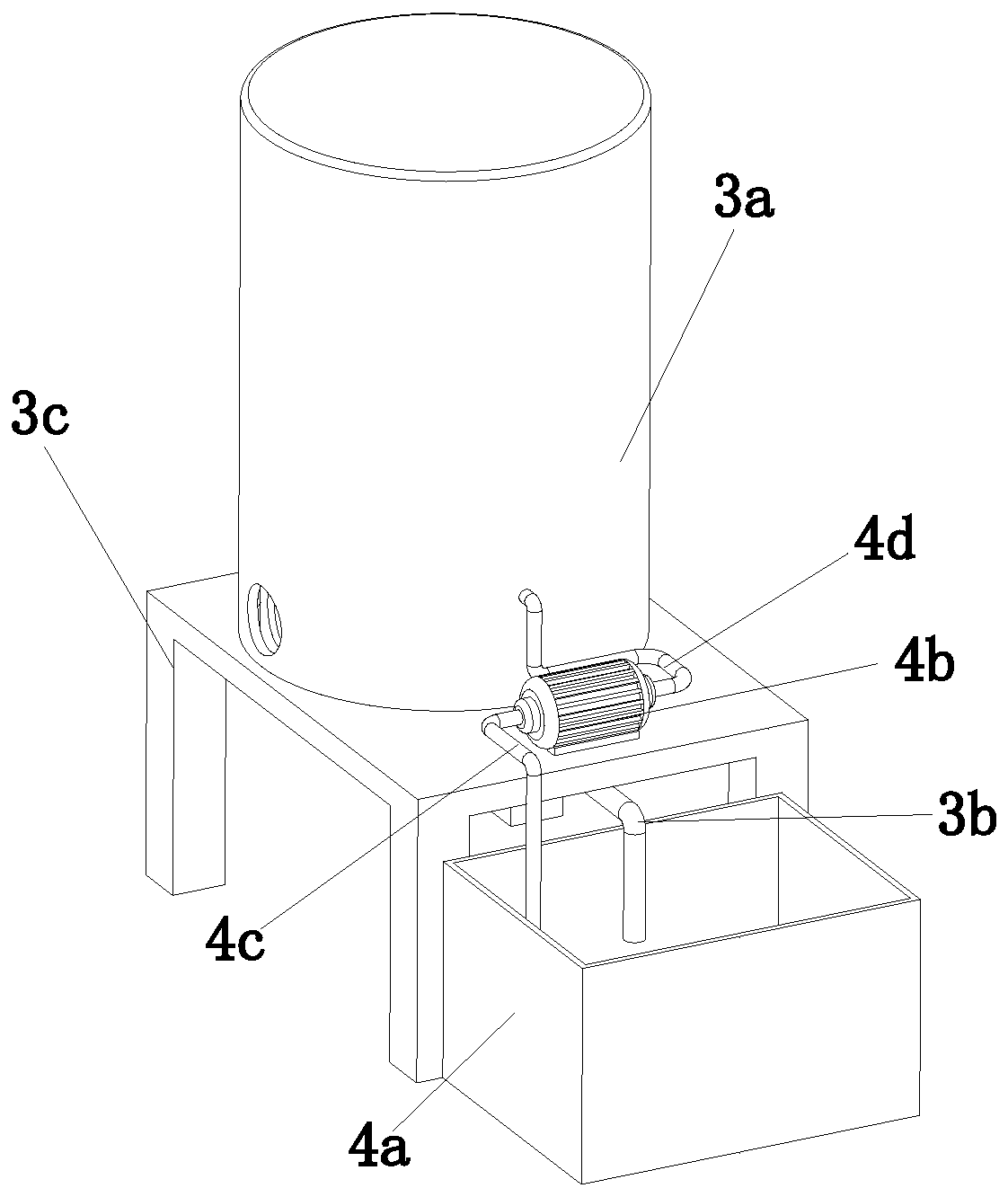
[0040] Embodiment one: combine below Figure 1 to Figure 7 As shown, the embodiment of the present invention provides a whitening treatment device for the tail gas of a drip mixing station, including a mounting frame 1, a flue gas heat exchange assembly 2, a spray assembly 3, a circulating water supply assembly 4, a steam-water separation assembly 5, an automatic adding medicine component 6, flue gas mixing component 7 and flue gas discharge component 8, the flue gas heat exchange component 2 is arranged on the side of the spray component 3, and the flue gas heat exchange component 2 communicates with the spray component 3, The circulating water supply assembly 4 is arranged on the side of the spray assembly 3, the circulating water supply assembly 4 communicates with the spray assembly 3, the steam-water separation assembly 5 is arranged on the installation frame 1, and the steam-water separation assembly 5 is connected to the spray assembly 3. The spray assembly 3 is connect...

Embodiment 2

[0057] Embodiment 2: With the continuous improvement of environmental protection requirements and the company's own emphasis on environmental protection, in order to completely solve the phenomenon of white smoke from the exhaust pipe, when the temperature is low in winter, there will still be a little white smoke with the above-mentioned treatment method. The adopted process is: adding a flue gas reheater after the above-mentioned treatment process.

[0058] The whitening mechanism of flue gas condensation reheating technology is as follows: Figure 9 As shown, the initial state of wet flue gas is at point A. After cooling down, it is condensed according to AD, then heated along DE, and then blended along EC and cooled to the ambient state point C. The change process of EC does not intersect with the saturated humidity curve, so there is no white smoke. The mechanism of white smoke removal shows that ambient humidity and ambient temperature have a great influence on the form...


PUM


Abstract

The invention discloses an asphalt mixing plant tail gas white smoke eliminating treatment apparatus, and belongs to the technical field of flue gas treatment. The asphalt mixing plant tail gas whitesmoke eliminating treatment apparatus comprises an installing frame, a flue gas heat exchange assembly, a spraying assembly, a circulating water supply assembly, a steam-water separation assembly, anautomatic feeding assembly, a flue gas mixing assembly and a flue gas discharge assembly, wherein the flue gas heat exchange assembly is arranged on the side of the spraying assembly, the circulatingwater supply assembly is arranged on the side of the spraying assembly, the steam-water separation assembly is arranged on the installing frame, the automatic feeding assembly is arranged on the top portion of the installing frame, and is further positioned on the steam-water separation assembly, the flue gas mixing assembly is arranged on the top portion of the installing frame, and the flue gasdischarge assembly is arranged on the side of the installing frame. According to the present invention, the flue gas treated by the flue gas heat exchange assembly, the spraying assembly, the circulating water supply assembly, the steam-water separation assembly, the automatic feeding assembly and the flue gas mixing assembly cannot present the white color during the externally being discharged, such that the unnecessary misunderstanding cannot be caused due to the colorlessness of the discharged flue gas.

Description

technical field [0001] The invention relates to the technical field of flue gas treatment, in particular to a whitening treatment device for tail gas of a leach mixing station. Background technique [0002] In the production process of the asphalt mixing plant, the screening machine screens the hot aggregate into several specifications, which flow into the corresponding hot material storage bins for storage. According to the set ratio, aggregates of different specifications are put into the stone weighing bin in batches in the order of small to large for cumulative measurement; at the same time, the hot asphalt sent by the asphalt supply device and the powder sent by the powder supply device are respectively According to the set ratio, put them into the respective metering devices for metering. After the weighing is completed, put it into the stirring pot according to the preset order for forced stirring. The stirred finished material is unloaded into the finished material...

Claims


Application Information

Patent Timeline
Patent Type & Authority Applications(China)
IPC IPC(8): B01D53/00B01D53/26B01D53/50B01D53/78
CPCB01D53/002B01D53/265B01D53/78B01D53/502B01D2258/02B01D2258/0283
Inventor 王红祥张澄金刚李国铭
Owner JIANGSU MODERN ROAD & BRIDGE
Learn More