A thermal reduction material mixing system with a rotary iron removal device

A material and mixing technology, applied in the field of thermal reduction material mixing system, can solve the problems of affecting the effect of iron removal, easy to be wrapped, easy to agglomerate, etc.

Active Publication Date: 2021-08-20
HEBEI SITONG NEW METAL MATERIAL CO LTD
View PDF17 Cites 0 Cited by
  • Summary
  • Abstract
  • Description
  • Claims
  • Application Information

AI Technical Summary

Problems solved by technology

However, some metal oxides contain iron or iron-containing inclusions in the production process; iron inclusions are also easily mixed in the process of material transportation or mixing, and the increase in iron in the alloy has a great impact on the performance of downstream metal products. Therefore, the content of iron in the alloy must be reduced; and the mixing equipment in the prior art often fails to meet the requirements for the mixing of materials with high proportion requirements and pollution prevention; and the currently used mixing equipment is Directly let the material pass through the iron removal device, so that it is attracted to the iron remover under the action of gravity, but when the material is mixed in the mixer, it is easy to agglomerate, so that the iron impurities are easy to be wrapped up, resulting in When it falls, it will not be attracted to the iron remover, which will affect the iron removal effect in the whole mixing process. Therefore, it is necessary to provide a method that can not only meet the requirements of high mixing ratio and high reliability, but also prevent the material from falling. There is no agglomeration phenomenon in the iron removal device to ensure the iron removal effect of the mixing system to meet the needs of special industries

Method used


Image

  • A thermal reduction material mixing system with a rotary iron removal device
  • A thermal reduction material mixing system with a rotary iron removal device
  • A thermal reduction material mixing system with a rotary iron removal device

Examples


Embodiment Construction

[0023] The following will clearly and completely describe the technical solutions in the embodiments of the present invention with reference to the accompanying drawings in the embodiments of the present invention. Obviously, the described embodiments are only some, not all, embodiments of the present invention. Based on the embodiments of the present invention, all other embodiments obtained by persons of ordinary skill in the art without making creative efforts belong to the protection scope of the present invention.

[0024] In order to make the above objects, features and advantages of the present invention more comprehensible, the present invention will be further described in detail below in conjunction with the accompanying drawings and specific embodiments.

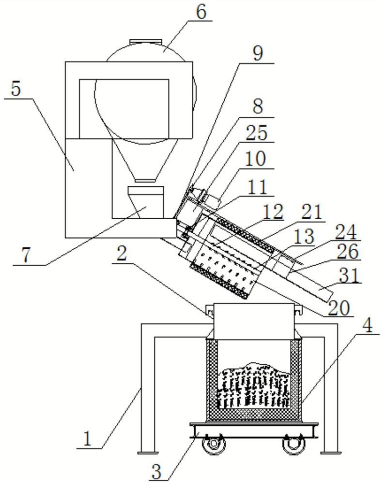
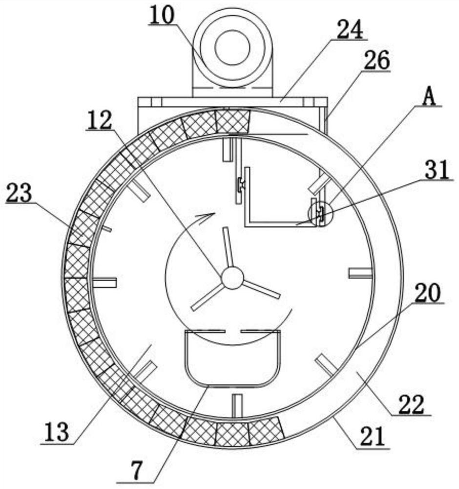
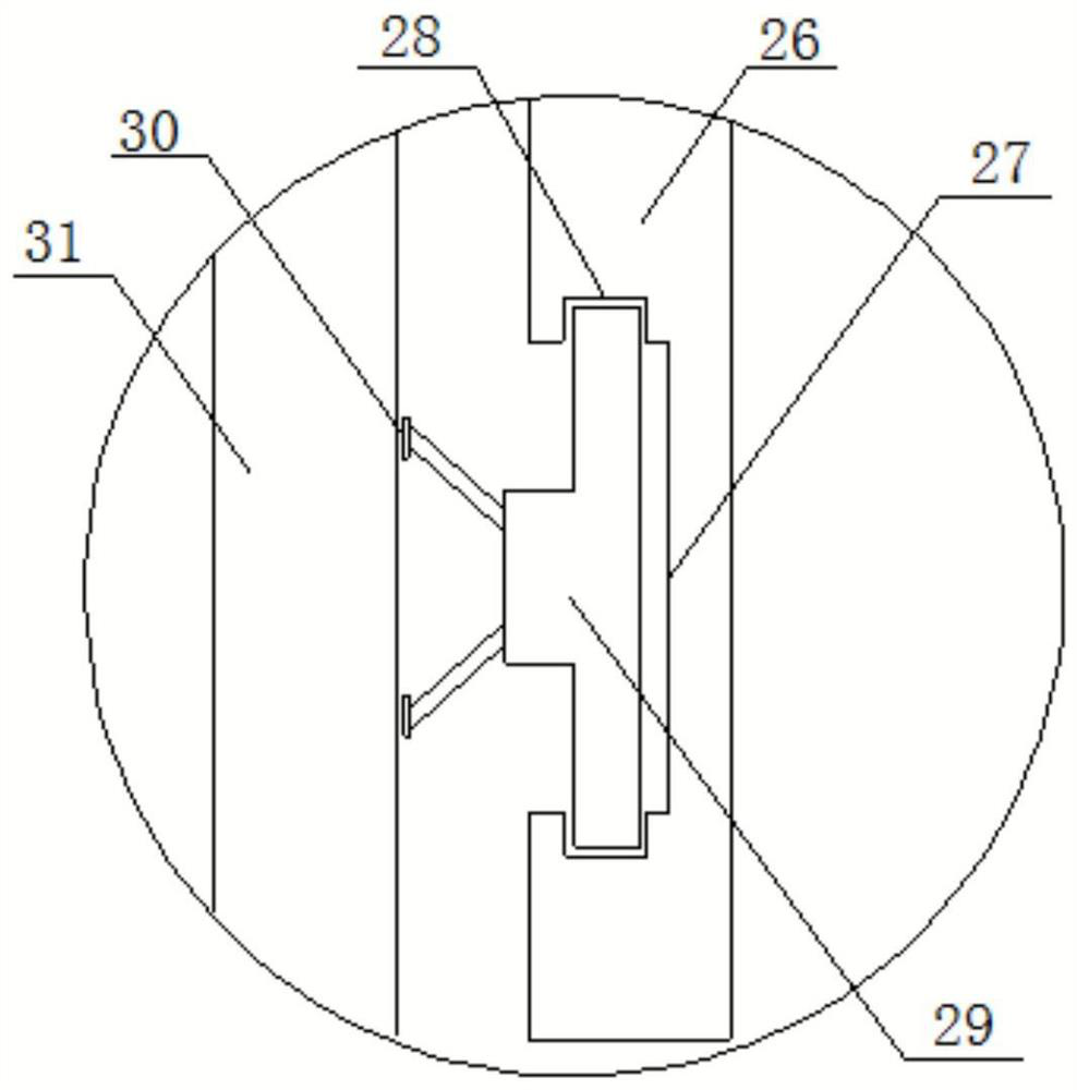
[0025] Such as Figure 1-5 As shown, the present invention provides a thermal reduction material mixing system with a rotating iron removal device, comprising a mixer 6, a stirring drum type iron removal mechanism...


PUM


Abstract

The invention discloses a heat reduction material mixing system with a rotary iron removal device, which comprises a mixer, a stirring drum type iron removal mechanism and a reactor, the mixer is fixed on a fixed frame, and the stirring drum type iron removal mechanism includes an Feed trough, power transmission mechanism, inner drum and outer sleeve, the inner drum and outer sleeve are installed obliquely, the feeding trough is movable on the inner drum, the inner drum is equipped with a stirring shaft, and one end of the power transmission mechanism is movable with the stirring shaft The other end is fixedly installed on the fixed plate, the mounting seat is fixedly connected to the bottom of the fixed plate, and the iron removal groove is installed in the mounting seat, the outer sleeve is sleeved outside the inner drum, and the lower inner wall of the outer sleeve is movable There are permanent magnet blocks, stirring blades are movable on the stirring shaft, and the reactor is movable on the platform truck; this material mixing system can not only stir to prevent agglomeration, but also ensure good iron removal effect and prevent iron impurities from affecting Perform secondary pollution while improving the reliability of the entire structure.

Description

technical field [0001] The invention relates to the field of material mixing equipment used in nonferrous metallurgy, ceramics and other industries, in particular to a thermal reduction material mixing system with a rotary iron removal device. Background technique [0002] At present, the mixing equipment used in nonferrous metallurgy, ceramics and other industries has low requirements for material mixing, and the mixing effect varies greatly. Common materials in nonferrous metallurgy production such as: material mixing for alloy production by thermal reduction method, metal aluminum powder The mixing with chromium trioxide, the mixing of magnesium powder and titanium dioxide, the mixing of aluminum powder and vanadium pentoxide all require to avoid the pollution of iron element in the process of mixing, and the thermal reduction method of metal is in the process of metal alloy In production, an elemental metal is used to reduce one or more metals from a metal oxide and form...

Claims


Application Information

Patent Timeline
Patent Type & Authority Patents(China)
IPC IPC(8): B01J19/00B01J4/00B01F9/08B01F13/10B01F15/00B01F29/64
CPCB01J19/00B01J4/001B01F29/4033B01F29/64B01F33/821B01F35/184Y02P70/10
Inventor 赵超乔敏王建东范建海
Owner HEBEI SITONG NEW METAL MATERIAL CO LTD
Why Eureka
Try Eureka